This signal ground to Star ground wire has caused a lot of confusion. The most common problem throughout this thread. It should be inserted in the first post in BOLD.
people are usually looking for files, without additional informing by reading something about files they have decide to download-and even when they read they remember what someone said how it sounds and similar, but rarely technical details. I believe "connect SGND to psu-gnd" is most written sentence in this thread...

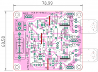
Hello brother, yes this PCB layout correct. Only one change, 2k2 resistance change with 1k or 820R or 680R.
I made that PCB on https://www.diyaudio.com/forums/sol...mate-fidelity-amplifier-1055.html#post5515173
Changed resistance value mark below
Regards
Thanks for helping, but this resistor influences the gain of the amplifier, I made the replacement but still didn't solve it, the bias continues at + -350mV in each 0r33 resistor and does not drop what can be done?
I believe "connect SGND to psu-gnd" is most written sentence in this thread...
So,...
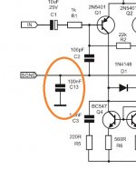
1) what is C13 there for?
2) why hasn't Mile ever solved this issue? A trick to keep the thread always on top?
Attachments
¹)well that is one new theory of conspiracy,latest these days...
²)when you have two or more channels then you connect all their inputs at input connectors,and from them you connect one wire to the psu-gnd. on that way you have omitted ground loop wich is a most common problem with wiring an amplifier.
do you really believe that whole this thread is based on this "trick"? what are you on, really? you should read a bit more...
Last edited:
Sir,
I have connected SGND to PGND by removing C13 (100nF) and replacing with 4.7 Ohms /2W Resistor and measured Bias Voltage at across the Emitter Resistors (at two ends), adjusted POT and obtained 26mV and relay clicked on (taken 3 seconds).
I convey my thanks to all the Members who helped me.
With regards.

Nice design Prasi.
At 40v rails what kind of wattage are we looking at?
At 40v rails what kind of wattage are we looking at?
APEX FX-12, interesting design.
regards
prasi
Please suggest me the best voltage setting of bias for APEX AX14P
With regards
about 15mV should do it just fine.
Sir,
I have connected SGND to PGND by removing C13 (100nF) and replacing with 4.7 Ohms /2W Resistor and measured Bias Voltage at across the Emitter Resistors (at two ends), adjusted POT and obtained 26mV and relay clicked on (taken 3 seconds).
I convey my thanks to all the Members who helped me.
With regards.
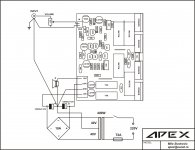
this is how it should be done properly,to avoid ground loop 100W Ultimate Fidelity Amplifier it is another APEX amplifier but the basics are the same.
Attachments
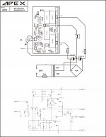
this is how it should be done properly,to avoid ground loop 100W Ultimate Fidelity Amplifier it is another APEX amplifier but the basics are the same.
That diagram doesn't show the power ground to the board.
That diagram doesn't show the power ground to the board.
Attachments
Good morning, I can't adjust my AX11 bias. In the tests the lamp remains on and biases with 350mV and each emitter. I've already changed all the transistors, i installed a 5k pot (in place of 4k7), checked for short circuits, but it didn't work, rotate the pot but do not change bias.
I made some measurements:
Differential pair: BC546
BxC=1,95V, 2,03V
CxE=1,31V, 1,37V
BxE=595mV, 594mV
BC546
BxC=2,70V
CxE=630mV
BxC=2,07V
BC639 and BC640
BxC= 2,03V, 1,95V
CxE= 1,37V, 1,31V
BxE= 594mV, 595mV
BD139 and BD140
BxC= 1,98V, 2,07V
CxE= 2,65V, 2,71V
BxE= 630mV, 639mV
BC517
BxC=2,72V
CxE=3,38V
BxE=661mV
2SC5200 and 2SA1943
BxC=2,65V, 2,68V
CxE=3,30V, 3,35V
BxE=672mV, 694mV
I forgot to measure mpsa92, if necessary I will do the measurement.
To help is welcome, thank you.
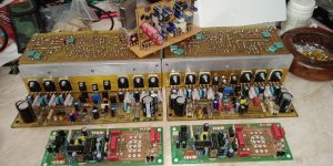
(I'm testing the amplifier on the right)
Does anyone have any guidance ??
Hello friend, my question is transistor Higher DC Current Gain (hfe) effect on amplifiers performance.
Please reply
Regards
Please reply
Regards
Hello friend, my question is transistor Higher DC Current Gain (hfe) effect on amplifiers performance.
Please reply
Regards
Amplify the base current. By increasing the base current, the collector current greatly increases, thus increasing the voltage over the collector resistor and the output voltage of the circuit decreases.
The little I know is this and I learned here on the forum !! My area is completely opposite to electronics, which is just for hobby and to hear a good sound !!
I made an exchange that you suggested, but it had no effect.
I changed all the transistors, I imagine that not all I have that are defective.
Nice design Prasi.
At 40v rails what kind of wattage are we looking at?
Thanks bigaudio. Being lat-mosfet, it should give around 55-60W rms into 8 ohms.
regards
prasi
- Home
- Amplifiers
- Solid State
- 100W Ultimate Fidelity Amplifier