The bias current is just the voltage across the output resistor divided by resistor value. So 3mV divided by 0r22 = 13mA on my amp.
If there is a DC offset some current will go to the speaker so check it without speaker connected. The bias should is the current through both output transistors not the speaker.
@nigelwright7557 - thanks for "dumbing it down for me", it really helped with the math, so thanks again.
@xrk971 - for the overview on what was "blown" you were pretty much spot on
@spookydd - for all the assistance, much appreciated.
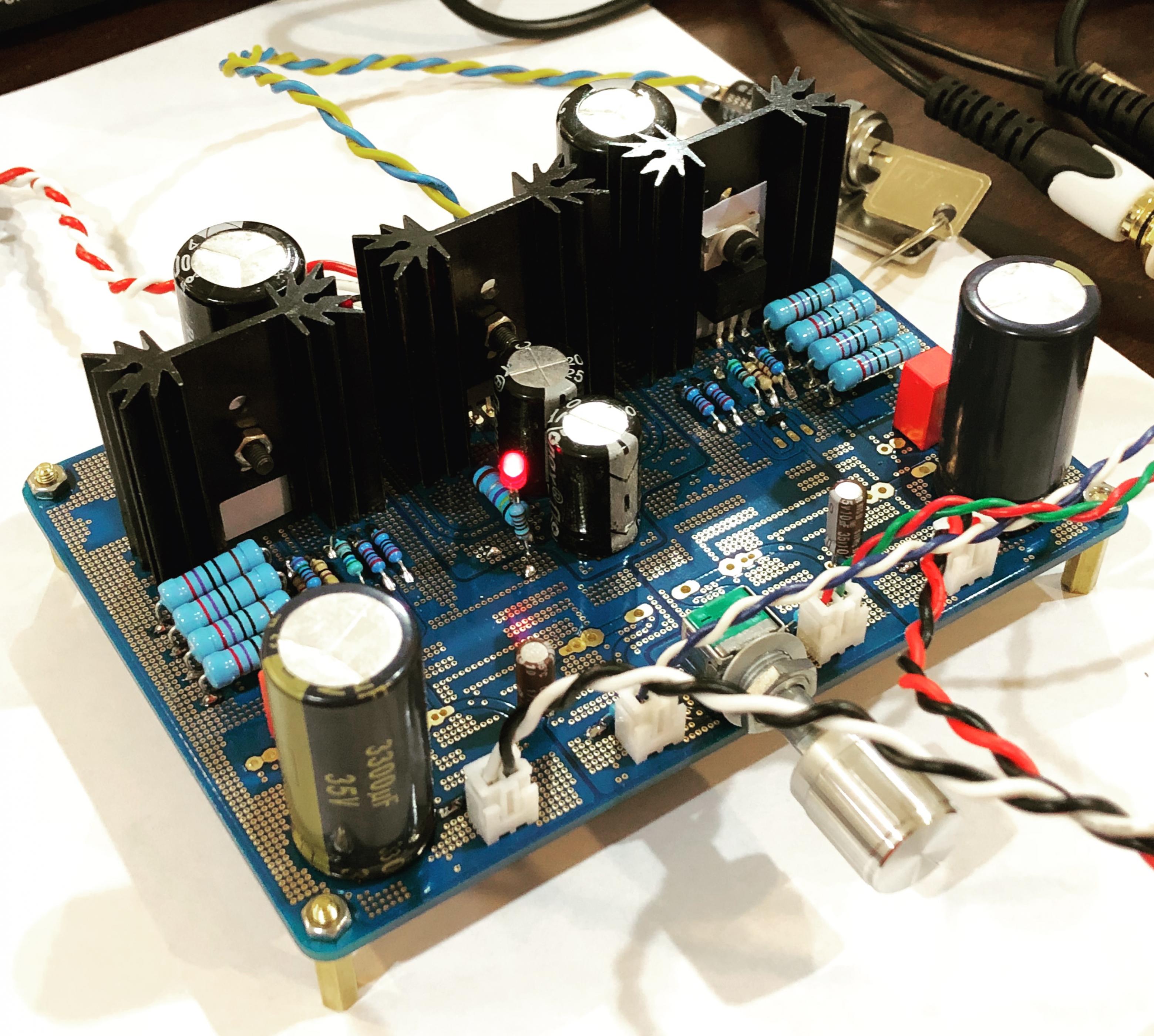
Well - I replaced the MOSFETs (4), 12v Zener Diodes (2), the Gate resistors (4) and Source resistors (8) (which I stupidly didn't check until I already replaced the other parts and put back on the heatsink - duh!!!!)
Anyhow - set the bias at 10mV on both channels and have it running off +/-40 Vdc PSU with 40,000 uF currently.
If you are on the fence - build this amp.
- I have B&K 200.2
- NAD 216 THX
- LM3886 Mauro Penasa design
and this is right up there with all of them and possibly better, and maybe even better with more Bias or a little more supply voltage.
Super clear, clean mids/highs and lots of bass authority - even at low volumes, which was surprising.
Thank you, Thank you, Thank you - can't wait to get the other 2 channels up and running. This will be the Amplifier for my MiniDSP 2-ways when I get them buttoned up and in the case.
Thanks APEX for the design and the Group for making it easy for us beginners to build a solid amp, for much less than a retail design!
Well appears I still have issue with the amp that blew up.
It works fine at +/-35 and 40, but when I hooked it up to a +/-60 PSU the boas just keeps running up, starts at 0.0, but within 30 secs it is at 20-25mV so I turn off the power to keep from blowing it again. I have turned P1 all the way down and it does the same thing - bias goes up and I have to turn it off.
Other channel works fine at +/-60, and I can set the bias right at 10mV without issue. Plays music and the bias never goes past 13-14mV. MOSFETs and heatsink stay 10-15 degrees (F) over ambient too. So it’s stable.
Any ideas on what may still be wrong with the other amp? I checked all resistors and voltages against the working one with the 40V PSU and everything was within spec +/-5%.
Thanks for the help!
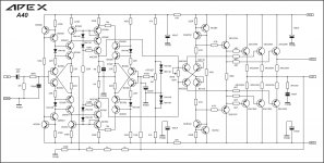
hi i need your help. i build a40 today when i connected supply there was 28v dc at output i adjusted the offset pot, nothing happened at this moment 100k resistor burned which is connected between output and offset pot. there is 470R resistor with offset pot in schematic that i used. but i have seen schematic with 470K resistor. i don't know which one is correct. also i have used 200R bias resistor as 100R was very hard to find in local market.I built my A40 with MJL 4281/4302. Plays beautifully.
Last edited:
Is the signal gnd connected to power supply 0v?hi i need your help. i build a40 today when i connected supply there was 28v dc at output i adjusted the offset pot, nothing happened at this moment 100k resistor burned which is connected between output and offset pot. there is 470R resistor with offset pot in schematic that i used. but i have seen schematic with 470K resistor. i don't know which one is correct. also i have used 200R bias resistor as 100R was very hard to find in local market.
yes it is connectedIs the signal gnd connected to power supply 0v?
here is schematic.
Attachments
Hi Rehman,
The series resistor to offset pot should be 470K.
Regards
Sha
The series resistor to offset pot should be 470K.
Regards
Sha
hi i need your help. i build a40 today when i connected supply there was 28v dc at output i adjusted the offset pot, nothing happened at this moment 100k resistor burned which is connected between output and offset pot. there is 470R resistor with offset pot in schematic that i used. but i have seen schematic with 470K resistor. i don't know which one is correct. also i have used 200R bias resistor as 100R was very hard to find in local market.
still same voltage and how do adjust it?Hi Rehman,
The series resistor to offset pot should be 470K.
Regards
Sha
Well appears I still have issue with the amp that blew up.
It works fine at +/-35 and 40, but when I hooked it up to a +/-60 PSU the boas just keeps running up, starts at 0.0, but within 30 secs it is at 20-25mV so I turn off the power to keep from blowing it again. I have turned P1 all the way down and it does the same thing - bias goes up and I have to turn it off.
Other channel works fine at +/-60, and I can set the bias right at 10mV without issue. Plays music and the bias never goes past 13-14mV. MOSFETs and heatsink stay 10-15 degrees (F) over ambient too. So it’s stable.
Any ideas on what may still be wrong with the other amp? I checked all resistors and voltages against the working one with the 40V PSU and everything was within spec +/-5%.
Thanks for the help!
Hi Bullitt,
Please mount the BD139 with circa 3in to 4in long flying leads (shrink tube the soldered legs) and bolt to the top of one of the IRFP240's. This will sense the thermal runaway much faster and reign it back in.
Other possible issue is that your MOSFETs are so mismatched that one of them is a current hog and all the current flows through it and thus it melts down. Use a transistor tester to measure Vgs on all of them. They will come out in ranges from 3.5v to 4.5v. If you have say two at 4.5v and one at 3.5v, that one is going to take the brunt of the current. Try to use reasonably matched MOSFETs (+/- 0.2 to 0.3 volts of Vgs)
Another possibility is that you have oscillation as voltage goes up, and this self-immolation occurs to the MOSFETs.
Do you have an O-scope? Look at output to see if it oscillates? Many times ultrasonic MHz oscillation and a visible sign of this is unstable bias as voltage goes up or time goes by. Unstable bias if you connect input source to audio in with volume turned down is also sign of oscillation.
Try changing C6 to 15pF to 22pF (silver mica is best, but NP0 or C0G is fine too) and see if that helps. Also try increasing C1 and C2 to 150pF or 220pF (220pF MKP film works here). If problem goes away, it is oscillation.
Last edited:
Hi Bullitt,
Please mount the BD139 with circa 3in to 4in long flying leads (shrink tube the soldered legs) and bolt to the top of one of the IRFP240's. This will sense the thermal runaway much faster and reign it back in.
Other possible issue is that your MOSFETs are so mismatched that one of them is a current hog and all the current flows through it and thus it melts down. Use a transistor tester to measure Vgs on all of them. They will come out in ranges from 3.5v to 4.5v. If you have say two at 4.5v and one at 3.5v, that one is going to take the brunt of the current. Try to use reasonably matched MOSFETs (+/- 0.2 to 0.3 volts of Vgs)
Another possibility is that you have oscillation as voltage goes up, and this self-immolation occurs to the MOSFETs.
Do you have an O-scope? Look at output to see if it oscillates? Many times ultrasonic MHz oscillation and a visible sign of this is unstable bias as voltage goes up or time goes by. Unstable bias if you connect input source to audio in with volume turned down is also sign of oscillation.
Try changing C6 to 15pF to 22pF (silver mica is best, but NP0 or C0G is fine too) and see if that helps. Also try increasing C1 and C2 to 150pF or 220pF (220pF MKP film works here). If problem goes away, it is oscillation.
In the process of changing out one mosfet (blew again) and the BD139 (to mount on irfp240) I pulled out two vias and 3 pads came off.
So my plan is to take as many expensive parts off this board, test them and populate a new board. I will use new mosfets, transistors and diodes to make sure if one of those was the issue it won’t carry over.
I plan to mount the BD138 to the IRFP240 and take that out as a possibility. Will take your other suggestions as “next steps” if it still is not working correctly.
Thanks for the assist - still learning, so specifics are a big help.
Pretty sure I read Apex say the A40 is the bestis it true that of all the Apex`s the best sound is not AX-14, but AX-17?
He also said FX8 was one of his favorite "small amps" - hence FH9, FH11, etc spawned from FX8. More transistors does not always sound better.
But he did say AX40 is his all-time favorite.
100W Ultimate Fidelity Amplifier
But he did say AX40 is his all-time favorite.
100W Ultimate Fidelity Amplifier
Last edited:
Hi Bullitt,
Sorry to hear about this:
But, you can salvage it by using flying leads on even the power MOSFETs (use flexible high current silicone RC car wire). Solder to exposed trace remaining attached to board. We now always use 2oz copper and use via stitching of two identical layers on 2 sides to increase conduction and durability (JPS64's trademark layout style).
For example:
I have yet to ever pull a solder pad off now.
Sorry to hear about this:
In the process of changing out one mosfet (blew again) and the BD139 (to mount on irfp240) I pulled out two vias and 3 pads came off.
But, you can salvage it by using flying leads on even the power MOSFETs (use flexible high current silicone RC car wire). Solder to exposed trace remaining attached to board. We now always use 2oz copper and use via stitching of two identical layers on 2 sides to increase conduction and durability (JPS64's trademark layout style).
For example:
I have yet to ever pull a solder pad off now.
Last edited:
apex 555 stere0
hello RSK could you share me apex 555 stereo pcb pdf
Only as my preference. I like to have indicator for fault and standby for the speaker protect. Built it and works great.
hello RSK could you share me apex 555 stereo pcb pdf
...Please mount the BD139 with circa 3in to 4in long flying leads (shrink tube the soldered legs) and bolt to the top of one of the IRFP240's. This will sense the thermal runaway much faster and reign it back in.
...MOSFETs are so mismatched that one of them is a current hog and all the current flows through it and thus it melts down.
...oscillation as voltage goes up, and this self-immolation occurs to the MOSFETs.
Try changing C6 to 15pF to 22pF (silver mica is best, but NP0 or C0G is fine too) and see if that helps. Also try increasing C1 and C2 to 150pF or 220pF (220pF MKP film works here). If problem goes away, it is oscillation.
So - I populated a whole new board, testing every component I took out of the old board and replaced if out of spec. I used all new BD139, KSA/KSC and IRFPs along with (1) of the 3 2N5551s that seemed a little low on gain.
The SAME issue persists - anything higher than ~50Vdc PSU on I can't get the bias to stay constant, It slowly moves upward +25mV (then I turn it off)
- on note, is that the other channel I can reduce the bias much lower, like down to 1mV, where this "problem" channel will not go lower than 8mV, regardless of PSU voltage (35, 40, or (48.5, which 60V PSU w 60W DBT in series - bias won't go below 12.5mV)
What I did differently this time:
-I mounted the BD139 with flying leads on top of the IRFP240
-I don't have a O-scope - so I can't test oscillation that way
-I don't have a curve tracer - only a cheap transistor tester, so I grouped the transistors by Hfe so the gain wouldn't be way off on any of them. Also confirmed with B&K multi-meter tester that has transistor function
-Oscillation - I will try increasing C6 and C1/C2 to higher values this weekend and hopefully will fix the runaway.
hi mr apex....please see in the pdf file in below...i design in proteus a new version of apex ax17 with 2pair c5200/a1943
plz chek this and say to me any mistakes or say upgrate .tnx again
s3.picofile.com/d/8363557634/178a4c9c-7ece-4a37-a230-6465f1a18c95/apex_ax17.pdf
oh dear apex what u dont answer about my fh11? when i power on 2n5551 be hot
power of music not bad....but when in first i turn on the power i have hi hoom in speaker...i cheked all of mistakes....but every thing be ok.....fh11 is realy a good amplifier?
i fear that my apex ax17 too dont woek prpperly....Similar of apex fh11
- Home
- Amplifiers
- Solid State
- 100W Ultimate Fidelity Amplifier