Thanks for the suggestion.
HAve you built it?
Kindly post the layout files/pdf.
Thanks and regards,
Sumesh
Yes I have built it. Works well. Here are the files.
Attachments
2SA1943,2SC5200 transistors manufactured by ON Semiconductor, are of good quality?
or you know where to order good quality?
thank you!
Nobody knows?

2SA1943,2SC5200 transistors manufactured by ON Semiconductor, are of good quality?
or you know where to order good quality?
thank you!
It is fake, go to NJW0302 and NJW0281 by ON Semi
Digikey and Element14 are authorized online sellers for On Semi. I doubt they would have fakes. However I have no experience with these transistors yet. I'm looking to build the A40 but find there could be more information for someone with basic amateur knowledge when compared to what information is in the Honey Badger Build and Universal PSU thread.It is fake, go to NJW0302 and NJW0281 by ON Semi
I feel like the A40 could be a better amplifier then the Honey Badger but the lack of organised information is killing me. I've read the thread over and over and feel like I've bearly gained anything. There are some very clever people here but I feel they must get bombarded too much with questions from simpletons like me, I dont blame them, they do it out the love of diyaudio.
I would love to see all the main designs in one thread with all the files and recomended part numbers and other useful information. It might help take the load off the main contributing members.
Anyways that's just my 2 cents.
I'm actually would love to contribute some funds to some just to get a bit of hand and to also say thanks.


Last edited:
Digikey and Element14 are authorized online sellers for On Semi. I doubt they would have fakes. However I have no experience with these transistors yet. I'm looking to build the A40 but find there could be more information for someone with basic amateur knowledge when compared to what information is in the Honey Badger Build and Universal PSU thread.
I feel like the A40 could be a better amplifier then the Honey Badger but the lack of organised information is killing me. I've read the thread over and over and feel like I've bearly gained anything. There are some very clever people here but I feel they must get bombarded too much with questions from simpletons like me, I dont blame them, they do it out the love of diyaudio.
I would love to see all the main designs in one thread with all the files and recomended part numbers and other useful information. It might help take the load off the main contributing members.
Anyways that's just my 2 cents.
I'm actually would love to contribute some funds to some just to get a bit of hand and to also say thanks.
View attachment 761596View attachment 761597
I don't know about ON Seni 2SC5200 only Toshiba.
Digikey and Element14 are authorized online sellers for On Semi. I doubt they would have fakes. However I have no experience with these transistors yet. I'm looking to build the A40 but find there could be more information for someone with basic amateur knowledge when compared to what information is in the Honey Badger Build and Universal PSU thread.
I feel like the A40 could be a better amplifier then the Honey Badger but the lack of organised information is killing me. I've read the thread over and over and feel like I've bearly gained anything. There are some very clever people here but I feel they must get bombarded too much with questions from simpletons like me, I dont blame them, they do it out the love of diyaudio.
I would love to see all the main designs in one thread with all the files and recomended part numbers and other useful information. It might help take the load off the main contributing members.
Anyways that's just my 2 cents.
I'm actually would love to contribute some funds to some just to get a bit of hand and to also say thanks.
View attachment 761596View attachment 761597
You could start a new thread for this a40 amp. I’m interested
I reckon a pure A40 thread with the latest info organised into the first post would be great. Have things like a working BOM for Digikey, have a walk through on the steps etc and lots of pictures. I really think it would be great and would make the amplifier even more popular and lower the experience level barrier required to build it. However I'm not in a position that could accurately develop and maintain it my knowledge on amplifier building is still very basic. But with help I could keep the first post organised. Ideally one of the main players that frequent this thread that has a working A40 build would be ideal for this role. It would be a thankless role but rewarding knowing your helping others.You could start a new thread for this a40 amp. I’m interested
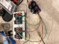
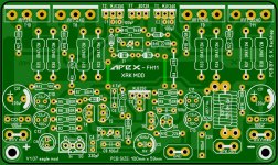
this is my Apex Vu, my pcb and with more leds (7), and everything okay, only the first LEDs flicker at high levels.
Regards
Roly
This vu-meter is from the T-Amp TSA2200 audio amplifier series.
FH11 Blew up - HELP
I finished putting together a pair of the FH11 so I have put it all together, double checked everything and tested on two different suplies (+/-40 and +/-35 Vdc) it plays music with either.
When I connected to my +/-60Vdc psu and it played fine for about 10-15 mins and then the Right channel went up in smoke. didn't feel hot after the first 5 mins of music at lower volume, so I stood back and a few minutes later it all went PooF!
Damage: All 4 mosfets and the 4 gate resitors are damaged. I checked all the other transistors and appears they survived (miracle).
I set the bias (or what I think is setting bias) by connecting my meter across the 0.47/2W resistors and turning the 1K pot to read 20mV across the resistor. I thought that would give me 42mA for each mosfet.
Again - noob here, but thought ~50mA per mosfet was fairly common practice.
Can someone PLEASE make sure this is how to set bias, what the correct mV should be and if I need to be aware of anything else before powering up again after replacing all the Mosfets and gate resistors?
P.S. - the other channel, set similarly still plays fine, granted I lowered the bias on it to 10mV just to be safe - mosfets barely get warm now.
Attachments

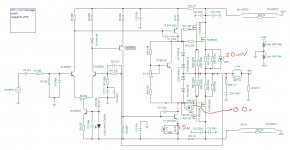
I can't edit - but I measured the 3 points indicated on the schematic on the working amplifier with +/-40 Vdc, in case that helps.
I have tried to turn P2, but does not have an effect on either VM2 or VM3 readings (kept track of the turns and put it close to where I started (which was 51r)
I have tried to turn P2, but does not have an effect on either VM2 or VM3 readings (kept track of the turns and put it close to where I started (which was 51r)
Attachments
I can't edit - but I measured the 3 points indicated on the schematic on the working amplifier with +/-40 Vdc, in case that helps.
I have tried to turn P2, but does not have an effect on either VM2 or VM3 readings (kept track of the turns and put it close to where I started (which was 51r)
The 1.5V from that VM2 shows about 32mA biasing the vas. Kinda strong maybe?
This is mosfet, so I doubt you'll see much, especially at idle, on R20. So nothing weird there.
The 20mV on VM1 means about 85mA bias in that mosfet. Seems on the "warm" side. (not class a, but on the way there...)
P2 is for correcting the output offset, and that's unlikely to have a visible effect on what's being measured.
I set the bias (or what I think is setting bias) by connecting my meter across the 0.47/2W resistors and turning the 1K pot to read 20mV across the resistor. I thought that would give me 42mA for each mosfet.
Again - noob here, but thought ~50mA per mosfet was fairly common practice.
Dude, there are 2 of those 0.47/2W in parallel there, so the 42mA you're thinking about, would go through one of them, but there are 2, so times 2, that's close to 85mA, not about 42mA.
Dunno much about mosfets, so not sure what's really common practice for idle current there, but this might run them a little warm, depending on how much heatsinking is there and fan or not...
P.S. - the other channel, set similarly still plays fine, granted I lowered the bias on it to 10mV just to be safe - mosfets barely get warm now.
Probably a good idea, or they get a little toasty.
Thanks for the reply -
How can I change that VM2 figure down from the 1.5v and 32mA to a better figure (I thought it should be 5mA but have also seen 20mA mentioned)
On VM1 I guess was a good idea I lower it to 10mV or ~43mA, I will keep it there for now. I couldn’t get any lower than 5.5mV. Hope that will be better.
Can you tell me how to check P2 measurement points? And what a good figure might be? Would like to check to make sure it is set correctly.
Hey Bullitt,
Thanks for building the FH11 and sorry to hear one channel went poof. I normally set my bias on the high side at 85mA or 20mV across the parallel 0.47R (effective 0.235R).
When an amp melts down after several minutes and all MOSFETs go, it may be thermal runaway due to the BD139 temp sensor not correcting fast enough. I would try this, connect the middle BD139 to flying leads and clamp it to the top of one of the IRFP240’s using same bolt that secures it to the heatsink. Add some thermal grease on the BD139 to make sure it had good thermal contact. Now it will respond with sub second time constant vs 30sec time constant when mounted on the heatsink.
Change out all the MOSFETs, if they are destroyed (use transistor tester or check ohms between pins -toasted one will show several ohms rather than circa 40k to 100kohm). Change the TO220 2SA1837 and 2SC4793 drivers, if damaged. They are usually bullitt proof (sorry, couldn’t resist 🙂) - I have yet to kill one. Check to make sure none of the gate stopper resistors are toast (measure open circuit).
Start it up with a 10R 10W limit resistor on each rail of PSU. Or if you have Variac, use that. Try 40v first and adjust bias. Then go to higher voltage.
Good luck!
Last edited:
How can I change that VM2 figure down from the 1.5v and 32mA to a better figure (I thought it should be 5mA but have also seen 20mA mentioned)
This isn't adjustable, it's wired in the circuit, and it's set pretty much by the values of R3/R4, so unless you changed both of those, there is no changing that standing current. I suppose you could bump those up a bit to perhaps 56 or so, maybe even 62 or 68 if the standing current in the vas is still overly high.
But 5mA could be on the low side. Might suffice though, since with mosfets there is no need to drive anything heavy with the vas. If this is the case then R3/4 could go as high as 320 or so.
On VM1 I guess was a good idea I lower it to 10mV or ~43mA, I will keep it there for now. I couldn’t get any lower than 5.5mV. Hope that will be better.
Well, 43mA doesn't seem that high, just a tad rich, but I don't know enough about mosfets, so not sure there. Reasonable it seems.
Can you tell me how to check P2 measurement points? And what a good figure might be? Would like to check to make sure it is set correctly.
That one is only there to balance the input stage, so it can minimize the output offset. So measuring how much offset is coming out of the output and bringing that as low as possible is what P2 is there for...
Keep that as low as humanly possible, no more than a few mV I'd say, but if you can do better, then go for it. But you might want to look at it over time, when the amp is warm and has been idling for some time. There will be some drift, so let it settle some more and readjust as needed. It might go higher when the amp is cold again, but will come down once it warms up. It's the warm condition that needs to be looked at..
I normally set my bias on the high side at 85mA or 20mV across the parallel 0.47R (effective 0.235R).
So you like them a bit toasty 🙂
I would try this, connect the middle BD139 to flying leads and clamp it to the top of one of the IRFP240’s using same bolt that secures it to the heatsink.
But I think those flying leads should not be overly long, or watch out for oscillations. Isn't that possible?
One other thing to do is isolate the metal from the db from the mosfet. Thermal grease alone won't isolate that.
Or if you have Variac, use that.
Not everybody can get their hands on a variac. Those are very useful, but not always so easy to obtain, depending on where you are, and perhaps depending on cost.
There is one other dirt cheap way to do this, if there is no variac, is to insert an incandescent light bulb (not too weak) in series with the transformer's primary. That does some good limiting in case of trouble...
I usually have a trimmer in the Vbe circuit.
Apply a sine wave and monitor output on a scope.
Turn up bias slowly until cross over distortion just goes.
Turning it up any further just generates heat and wastes power and puts the amp nearer thermal runaway.
Been doing it that way for about 10 years and never had a problem.
Peavey are also big fans of low bias.
All good ideas and suggestions, so thanks - a lot of stuff I should have asked about before powering up.
Sadly been looking at Variacs on Amazon (inexpensive China ones) but have not bought one yet.
I do use a DBT w/ 40w, then 60w bulbs before powering up without it.
Also have 2 DMMs, which I thought would help, but it was my math skills that let me down it appears with setting the bias too high for the heat sink possibly (no fan currently).
Just starting out, so a noob with noob tools at the moment.
Also have 2 DMMs, which I thought would help, but it was my math skills that let me down it appears with setting the bias too high for the heat sink possibly (no fan currently).
.
The bias current is just the voltage across the output resistor divided by resistor value. So 3mV divided by 0r22 = 13mA on my amp.
If there is a DC offset some current will go to the speaker so check it without speaker connected. The bias should is the current through both output transistors not the speaker.
- Home
- Amplifiers
- Solid State
- 100W Ultimate Fidelity Amplifier