e
i made fh11...in first i see that mje350 & 2n5551 be very hot...i have hi bias sound not very clear....but mr apex tell me replase 150R with 330R...i do this and result be very good....it work properly and sound be clear and good ..
but i have just a few hom nois
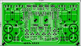
pleas see my pcb design in this link:
http://s4.picofile.com/file/8363574750/IMG_20190403_192542.jpg
MJE350 must have a heat-sink, if you don't, it will run VERY hot (mine is warm with a finned heat-sink)! When I blow air over this transistor the bias decreases, so this certainly could effect other components.
I have no "pop" at turn-on or turn-off, just instant music on turn-on and then a very long fade out when powered off (5-10 secs).
You may have a "current hogging" problem due to mismatched output MOSFETs. You can reduce bias current by increasing the big power resistors from 0.47R to 0.68R for example.
Is there a way I can check to see which is the current "hog" (without a curve tracer, or similar)? I would like to pull and test to see if I can replace easily.
Especially since I plan to populate 2 more boards over the next month or two.
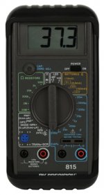
I have two DMMs, a Chinese transistor tester and a B&K Precision tester (which has settings for Hfe and other transistor parameters - see photo) at my disposal.
Attachments
hi. yes i use a mini heat sink and no problem about this ..after 30 minutes every thing be ok...just tell how i kill pop up nois....MJE350 must have a heat-sink, if you don't, it will run VERY hot (mine is warm with a finned heat-sink)! When I blow air over this transistor the bias decreases, so this certainly could effect other components.
I have no "pop" at turn-on or turn-off, just instant music on turn-on and then a very long fade out when powered off (5-10 secs).

i forget that apex fh11 have good sound....
my problem : when i turn on power have pop up nois and for 4 second have dc out pot nois...this terminate after 3/4 second...what i have this problem? help meeee plz
Last edited:
There are multiple 100w amps referenced in this thread, which one specifically are you wanting to verify?
Most popular are FH9 and AX14.
I am interested into AX14. And I would like to avoid incorect layout - eg diode reverse polarity. The fact is I would not discover it, I am not that experienced
I am interested into AX14. And I would like to avoid incorect layout - eg diode reverse polarity. The fact is I would not discover it, I am not that experienced
hi...please see my ax17...
apex ax17
Nice work.
Attachments
Is there a way I can check to see which is the current "hog" (without a curve tracer, or similar)? I would like to pull and test to see if I can replace easily.
Especially since I plan to populate 2 more boards over the next month or two.
I have two DMMs, a Chinese transistor tester and a B&K Precision tester (which has settings for Hfe and other transistor parameters - see photo) at my disposal.
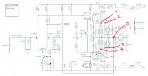
With amp running measure the voltage drop across individual source resistors to see which one has excessive current vs the other. Measure current between test point 0 and 1/2 and 0 and 3/4 (see sketch). When you match the MOSFETs use the tester that tells you Vgs with MOSFET removed. Buy a bunch of them (like 12 or more - you will use them so don’t worry). Write the Vgs value with a sharpie or pencil on the mosfet for future reference. Values will be from 3v to 4.5v, tru to get within 0.2v or better. Perfect match is luck of all from same tube or some times need to buy 50. There are places that sell matched MOSFETs. But generally if you get 12, you will fine 4-6 that are close enough.
You may need a better tester like these:
12864 Mega328 ESR Transistor Resistor Diode Capacitor Mosfet Tester w/ Test hook | eBay
Attachments
Last edited:
Nice work.
hi dear apex...i just copy your schematic.....you'r work its nice and perfect...
about fh11 with 330R my problem be ok perfect....but i have pop up when power be turn on and a few hom noise that volume is down can hear it..what i do?
and why in the caption on the Board AX-19? Or AX-17 with two pairs of output transistors has called AX-19?
apex ax14: have 14 transistor
ax17:have 17 transistor
ax19:ax17+2transistor
With amp running measure the voltage drop across individual source resistors to see which one has excessive current vs the other. Measure current between test point 0 and 1/2 and 0 and 3/4 (see sketch). When you match the MOSFETs use the tester that tells you Vgs with MOSFET removed. Buy a bunch of them (like 12 or more - you will use them so don’t worry). Write the Vgs value with a sharpie or pencil on the mosfet for future reference. Values will be from 3v to 4.5v, tru to get within 0.2v or better. Perfect match is luck of all from same tube or some times need to buy 50. There are places that sell matched MOSFETs. But generally if you get 12, you will fine 4-6 that are close enough.
You may need a better tester like these:
12864 Mega328 ESR Transistor Resistor Diode Capacitor Mosfet Tester w/ Test hook | eBay
That is the exact tester I have and I used it to match all the transistors as close as possible out of the 20 of each I had. According to the tester all the 2N5551s/MOSFETs were within 1% (Hfe and Vf) and I chose ones with the same specs for both MJE350s and BD139s for all boards.
Thanks for giving me the points to check - will try and see if I can figure out the "current hog" over the next couple of days.
Ah!! There it is! -)) -)) So the apex ax-14th with two pairs of output transistors called apex АX-16!
amost yes...this name's is optional ....apex ax16 have mor transistor ..you can download apex ax16 in belllow
APEX AX16 AMP.RAR — Yandex.Disk
Nice work.
hi apex...can i replase 4793/1837 with tip41c/tip42c or mje15031/15032?
i know that pin's be diferent.
in my country 4793/1837 be very expensive or dose not excist.
sorry my english.
That is the exact tester I have and I used it to match all the transistors as close as possible out of the 20 of each I had. According to the tester all the 2N5551s/MOSFETs were within 1% (Hfe and Vf) and I chose ones with the same specs for both MJE350s and BD139s for all boards.
Thanks for giving me the points to check - will try and see if I can figure out the "current hog" over the next couple of days.
Well, probably not a "current hog" situation then. But do measure the current anyway. Very puzzling since you repopulated a new board and the problem remains. Are the thermal contacts on all the MOSFETs good? An IR thermometer (or your finger) will tell you which one is hotter than others. Are you using silicone insulator pads, or mica and thermal grease? Either should work fine. One final thought is the quality of the 0.47R source resistors. Cheap no name bright painted blue ones from eBay/Aliexpress can often be unreliable and blow like a fuse (go open circuit). Best ones are Panasonic ERX series, or Vishay/Dale. They are like $0.6 ea though but worth it as they also will reduce distortion.
Please post a closeup detailed high res photo of your amp that is giving problems. A bottom side phot as well. Finally, double check all your resistor values to make sure you are not off somewhere. Slipping a factor of 100 to 1000 is not uncommon (like 470R vs 470k etc).
I will get you some high quality pictures.
The 0.47 2W Resistors are KOA Speer (M-Ox) bought from Mouser (as was everything except the transistors - those were from Arrow/Digi-key)
I checked every Resistor, Cap, diode, transistor, mosfet for being within spec before installing on all the boards - which I agree makes it odd that problem stayed with new board and original works perfectly. I have also gone back twice and checked the resistors - thinking I missed one, but they all checked out.
As far as mounting - I am using 4-40 hex bolts, with a #4x3/8" flat washer and Avid thermal pads and went back and torqued all bolts after letting it run for an hour at +/-40Vdc, in case the heat effected them.
I have used a IR thermometer and nothing seems overly hot have not measured more than 120F anywhere on board, heat sink or component. I can keep my hand/finger on heat-sink/component without any discomfort.
- MOSFETs ~85F on front and 100F on back/heat sink
- small transistors are ~80F
- MJE350 ~95F, but heat sink stays ~80F
- BD139 was ~80F, but now on top of IRFP240 is about ~90F
- Heat sink - found a couple times it hit ~120F, but that was at +/-65Vdc and only after running pretty loud music for 20-30 mins. Generally it is ~95F at the bottom and ~80F at the top (size is 5"H x 10"W x 1-1/2"D(w fins)) and have both channels on one heat-sink (plan is to have a total of 4-channels, with 2 boards on identical heat sinks if I can figure out problem(s))
Thanks for hanging with me and offering guidance.
Bullittstang,
I had to look back through the thread. It was three years ago since I built the FH11. I don't think I ever got rid of the turn-on thump. I had to use a protection board with a delay. I moved on building many other amps afterwards so I really only remember this build by reading what I wrote in this thread. I really can't offer more help than that.
Blessings, Terry
- Home
- Amplifiers
- Solid State
- 100W Ultimate Fidelity Amplifier