G: The BD139 or BD140 will work well in the same place provided the variable resistor is located in the base emitter section. Otherwise I don't see any difference apart from polarity issues. It's only a voltage multiplier.
OK if you are sure about that keep it the same way
")
I made my PC board for the P3A but that project is far from test.
One advantage in the favour of the Darlington does not need any preamplifier.
I don't think many people built these amp, specially not 100% after the schematic using the recommended components.
That way to compare the two amp would somehow unfair.
I'm just kidding
I just got bored a bit to tell people (repeat myself) it worth to build these little amp specially for that small investment or how good does sound etc.
Of course I help if someone interested to build one.
Greetings G
......It would be good to test the drivers with out heatsink and with heatsink I mean to make some measurement.
I never did it.........
..........Be careful with the 2SK246/J103 those are not the same like the 2SJ74BL/2SK170BL............
.......... BD140 you need on the heatsink, also it influence the bias set up. I'm amazed the amp works properly with the BD139 to..........
.......... I used a lot of parts it does sound good with most of them but with the rightly matched components it is incredible good.........
Hi G,
Yes I will test the drivers with and without the heat sink. I must monitor the supply voltage as I think it does vary with that also. Maybe I should check the temp too.
The 2SK246 is used at the input of several designs. It isn't exactly the same as 2SK170 but I believe it can be used. The trans conductance of the 246 is much lower than the 170. Would impact the harmonic content I guess due to lower OLG.
Check out OAMLabs A500 5x100W Channel Monobloc MOSFET Amplifier
Has a cascode at the input. 2SK246/2SJ103 BL was used.
You are right about parts sensitivity. One needs to actually try out different parts to see if there is an audible difference. As usual we need to be very careful to ensure that the mind doesn't play tricks when switching parts !
Last edited:
Hi Ashok and Gabor ,
Ashok , DC offset stability is input stage temp dependent ,
it should be lower once you put your boards + heatsink
on vertical position.
If the VBE multiplier doesnt allow for high enough current
just reduce the resistor that is in serial with the trimmer
by taking the imediate inferior value , 390R.
Gabor , hope all is going well and that you finaly found
the good balance in this simple design of yours.
Look to see furthers results from Ashok s experimentation ,
i ll probably build a proto if ever more debbugging is required.
Hello Wahab,
Thanks for your comments. The bias current problem was due to something else. A problem with one of the supplies. That was fixed and everything is working well.
I was not worried about output dc offset ( which is quite low already ) and didn't drift enough to cause concern. But the output dc bias varies quite a bit and now I think it is psu related mostly. Our mains supply varies quite a lot and causes the dc supply to fluctuate.
That's why I said that I will monitor the supply voltage while checking the dc bias. But so far it hasn't gone out of control. In fact it appeared to be over compensated and dropping with temperature. But I cannot say this for sure because I noticed it just a few minutes before I went to bed. It does however start very low and then builds up to a peak after several minutes which is quite normal.
This is why I have to do a controlled test. I do not have time right now. Maybe tomorrow. Meantime when I get time I will listen to it.
Last edited:
No...............The BD139 or BD140 will work well in the same place provided the variable resistor is located in the base emitter section. Otherwise I don't see any difference apart from polarity issues. It's only a voltage multiplier.
A PNP needs to be inserted to suit it's polarity. That requires the Vr to be in the upper leg of the resistive divider.
If you change to an NPN the be junction is now the lower of the pair and the Vr must be moved to suit the NPN.
Hi G,
The 2SK246 is used at the input of several designs. It isn't exactly the same as 2SK170 but I believe it can be used. The trans conductance of the 246 is much lower than the 170. Would impact the harmonic content I guess due to lower OLG.
You are right about parts sensitivity. One needs to actually try out different parts to see if there is an audible difference. As usual we need to be very careful to ensure that the mind doesn't play tricks when switching parts !
ashok
I didn't wrote you can not use that JFet!
Just not the same and it may not be direct replacement for the BC550C/560C because it is not direct replacement to the 2SK170/2SJ74 that is sure.
One can modify the circuit to use the type of device he has or he likes but in that case I have to say we do no longer talk about the same amplifier.
It will be the same topology but not the same amp.
It can sound great or even better than mine but since you live fare and you can't listen my amp or me yours we do not have a clue the sound you achieved or I got.
These are facts, I hope you agree with those.
There are several amplifier same topology on the forum but not the same as mine.
So I have no idea about those performance.
I do want to test the LazyCat amplifier to get some information about.
I must build the amp to compare with mine..
When I posted the circuit someone right away replaced the power darlington with common BJT and made several sim test.
Do you think he get any information about the circuit I posted or the amp now I listen?
No, I don't think so.
He is a smart guy, I do respect him, he designed a famous and great amplifier, do you think he doesn't know he can not replace the power darlington with a simple BJT.
I guess he knew very well!
So what was the purpose?? I really don't care.
From now on when someone replace parts in the circuit only comment I can ad same topology, similar amp but not the same.
So the performance of the amp can not be, and no way to be the same!!
We only can comment the performance of the amp we built or listen.
Best way to avoid the mind play tricks when you do test or try to improve an amplifier just do it on one channel and please ad do A-B test..
In case of sound stage test etc we need to build one more amp so we can test it as a Stereo.
Please do not take any of the above mentioned personally!
I'm happy you built a amp based on these schematic and you like it a lot but I have no clue about your amp performance.
Can be better than mine, can be the same or can be worst, these case who knows.
Greetings G
No.
A PNP needs to be inserted to suit it's polarity. That requires the Vr to be in the upper leg of the resistive divider.
If you change to an NPN the be junction is now the lower of the pair and the Vr must be moved to suit the NPN.
Come off it Andrew. You must be kidding ! Doesn't it look like I know that ?
I designed the pcb so I should have known what I was doing ! Let's not bother about this anymore. There are other things to be checked and time as usual is in short supply..
Hi G,
You are right. To get to the stage you were in , one has to build it exactly like you did. Changing anything could alter the sonic signature and it's not possible to describe that exactly on the forum.
I'll build one of your boards, but not immediately. But I appreciate your concern that I should build one exactly like you did ! Only this will validate a comparison.
Your concern that the 2SK246/2SJ103 might be very different from the 2SK170/2SJ74 is possible but not easy to guess. One will have to build it to find out.
So it again boils down to building "your" board with your circuit components and values to get to your reference point. That sounds reasonable.
Fine. Will do that.
Since I find it inaccurate making a copy of your board design I quickly make one myself identical to your layout. However I moved the parts closer together and got a board size of 95x60mm . I will not be making it now but had some free time during which I decided to see how small I can make your design. Maybe it can be reduced a bit more. I even put the emitter resistors on board because they are much smaller than your resistor . However the board still has some jumpers underneath for these resistors.
It's going to be a very busy weekend and so I might not have much time except check the old board. In fact it's going to be a very busy month end. Lots of serious work has to be completed.
Cheers.
It's going to be a very busy weekend and so I might not have much time except check the old board. In fact it's going to be a very busy month end. Lots of serious work has to be completed.
Cheers.
your words give me the impression that you think everyone understands, but to me they are ambiguous and confusing.Come off it Andrew. You must be kidding ! Doesn't it look like I know that ?
You seem to be confirming the idea that simply swapping PNP and NPN in the Bias voltage generator is OK.
It is not. The PCB, unless specifically designed to allow that swap, will not conveniently permit a simple swap.
Can you post your lay out please or PM it to me please..
May be we can learn from each other some new tricks.
In my design try to use as little jumpers as possible, I prefer one sided board for audio instead two.
Those type of 5W resisters has magnetic leads most of them.
I use those type to from Fukushima, Panasonic etc they are all magnetic type and not better than the common Yageo or Royal cement type.
Better chose if we could get 5W 1% metal film resistor for emitter or 2PC 3W type.
Wahab I didn't tested yet the mosfet amplifier, I really feel bad about that.
Just need those diodes ad trimmers to test that amp.
I was busy with some amplifier enclosures and other work at my free time but still I supposed to test that amp way back.
For the darlington which was modded by you only I made the PC boards yet.
I will test thoroughly that soon, for test I buy regular resisters at first.
I want to test if the stability of the amp get improved. If yes and the sound remain the same I do build that later with exotic parts.
Also I'm planing to test the mosfet version but not now.
First I must test of the Hitachi mosfet amplifier.. Only need to spend on that 10-15 bucks.
Probably next week I buy those diode and I put together the amp at least on a piece of plywood.
Greetings Gabor
Last edited:
your words give me the impression that you think everyone understands, but to me they are ambiguous and confusing.
You seem to be confirming the idea that simply swapping PNP and NPN in the Bias voltage generator is OK.
It is not. The PCB, unless specifically designed to allow that swap, will not conveniently permit a simple swap.
Hi Andrew,
You are right. I realised later that there are others too who would not have understood it the way I mentioned it. Apologies !
Unfortunately I couldn't delete the post I made after I realised what was wrong about it. It had already crossed the half hour limit to edit it.
No offence meant. Shall be more careful when replying to posts !

Hi gaborbela !
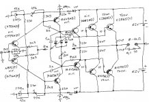
Want to try to DIY for myself pair of SS AB class Amp based on yours old symmetric Amp design , but instead of output power Darlington`s implemented with original discrete BJT components which come from one old discarded & horrible sounding Japanese PA Amp , relative big heatsinks come from same source to .
Here is my idea & proposed schematic , which can be further modified anyway !
Personally have no big experience building SS Amps , so what do you think about this schematic ?
Thanks in advance !
Attachments
Hello
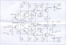
These circuit will give you some idea, but these not my amplifier..
I did tested something similar and I run back to the Darlington.
Again you can use your own transistor set but most of the time is better to build something after a proven circuit specially if you are not an experienced guy.
Please forget that high voltage PS even if you would go with 2 pair power transistor specially if you would like to bias the amp for the first watt or so in to Class A.
There are several good sounding amplifier readily available at the forum built and tested by many DIY-ers, would be much easier to achieve a good result.
In case if you like these topology and you want to build something similar please use these circuit for starting point, but I have no idea about these circuit how will perform specially with your transistor set.
Greetings Gabor
Attachments
gaborbela thanks for you answer !
Yes I have no big experience building SS Amps , mostly I have build & designed tube Amps ( OTL) , but I have plenty of experience repairing & tuning SS Amps , doing that everyday profesionaly as TV mechanicus .
Anyway I will continue to experiment with this specific topology from my attached schematic .
I think that your`s Amp topology and very similar amp topology from Mr.Bruce de Palma deserve some attention .
BTW ,
until now only SS Amp with acceptable good sound for me it is by me heavy modified old Revox A78 , which play music 24/7 in my kitchen, for many years I have try to use and listen many different SS Amps without any success .
Best Regards !
I ran some bias tests. With a +/- 40 volt supply and one pair of TIP142/147 and the heat sink shown I find that the bias drops with time if the bias is set lower than 100mA. At or higher than 100mA it keeps rising slowly as the heat sink warms up.
So it appears for bias stability you need to use less than 40 volt supplies and larger heatsinks and more output pairs. I'd guess two pairs of output devices with +/- 35 V and a larger heatsink should be stable at 100 mA.
Of course with the Lat FET version this problem disappears.
With a fan cooling the heatsink the problem appears to go away !
Note: With just over 100mA bias the heat sink reaches a temperature of 40 deg C with an ambient of 30 deg C. The driver transistors with a small aluminum heat sink reaches 33 ~ 34 deg C.
Last edited:
Member
Joined 2009
Paid Member
I agree with others here that it does seem that starting out with +/-62V is increasing the chance of thermal runaway. But you can help a lot if you increase the size of the VAS emitter resistors. Instead of 220R use more like 2K2 ohms. Put some big capacitors in parallel with these resistors. The capacitor will ensure you still have good gain at audio frequency but the large value resistor will help stabilize the VAS current. They will also drop some voltage so you will lose maybe +/- 10V of headroom but I think you can readily afford that with such high voltage rails. It would be better if you start with lower voltage rails.Personally have no big experience building SS Amps , so what do you think about this schematic ?
In a push, you could build each channel using only one half of the secondary, so that you have two single rail amplifiers, one with +62V rail, the other with a -62V rail. In each amplifier you must use an input and an output coupling capacitor. The two channels will then have half the total voltage, equivalent to more like +/- 30V and they will be well decoupled from each other since they will not share power rails. And if you wanted to provide a means to inver the input to one amplifier you might be able to bridge them (would have to think about that).
Last edited:
I ran some bias tests. With a +/- 40 volt supply and one pair of TIP142/147 and the heat sink shown I find that the bias drops with time if the bias is set lower than 100mA. At or higher than 100mA it keeps rising slowly as the heat sink warms up.
So it appears for bias stability you need to use less than 40 volt supplies and larger heatsinks and more output pairs..
Now you understand why I wrote 40V to high for 1 pair darlington especially if you push the amp hard.
The same reason I mentioned the heatsink size.
I know these amplifier like the back of my hand. 20+ years testing, trying to improve etc that a lot of time.
Out of experience I wrote about the driver transistors to.
I did tested 3 different pair from Toshiba only highly recommended by experienced guys.
I can look up those transistors and post picture, but do I need to make someone belive.
Plus many other driver from other company was tested...
I can write the same about most of the parts I use, they where thoroughly tested and tested!!!
The reason I asked if someone really want to listen and test these amp or compare the amp at first may build after the circuit.
I did biased the amp 250 mA at 37V rail Voltage one pair darlington
I do want to test the modded version, according to wahab that will be more stable.
To build these amp with LAT fet, great idea but I think the mosfet has to be carefully chosen to these project specially if the speakers already has a bit soft or slow bass.
For example EXICON Lat fet has much controlled deeper bass than Hitachi.
I'll test it later the mosfet version but I'm happy how she perform with the darlington..
I just read today the LC mosfet VSSA amp was compared by someone the Hitachi with the Alfet.
The Alfet sound better according that fellow DIY-er.
Greetings Gabor
- Home
- Amplifiers
- Solid State
- My first DIY amplifier 20 years a go