The fact both boards have different symptoms points to a construction error/parts error somewhere.
Some key basic checks are:
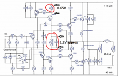
1/ The voltage across the 100 ohm in the current source. It should be around 0.65 volts.
2/ The voltage across the bias setting resistor should be around 1.2 volts and vary as the resistance is altered.
If you link out (short out) this setting resistor then Iq should fall to zero. If it doesn't then there is a problem in the final stages, driver and outputs.
Some key basic checks are:
1/ The voltage across the 100 ohm in the current source. It should be around 0.65 volts.
2/ The voltage across the bias setting resistor should be around 1.2 volts and vary as the resistance is altered.
If you link out (short out) this setting resistor then Iq should fall to zero. If it doesn't then there is a problem in the final stages, driver and outputs.
Attachments
mooly amp
Incidentally, I would post pictures of the sine wave on my scope but I have no idea how to do that or post pictures of drawings.
Thank you.
Incidentally, I would post pictures of the sine wave on my scope but I have no idea how to do that or post pictures of drawings.
Thank you.
Are Prasi's gerber files for the slimmer width PCB posted somewhere? I couldn't find them in the thread.
I cant remember if I posted them, here they are.
regards
Prasi
Attachments
-
gerbers_mooly mosfet amp prasi_rev2.2.1_2pair_fb res_recovered2_2019-08-02.zip717.9 KB · Views: 790
-
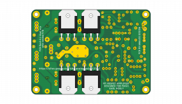 3d1 compact (3).png466.6 KB · Views: 2,204
 -
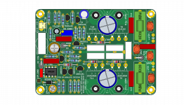 3d1 compact.png721.2 KB · Views: 2,006
 -
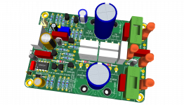 3d3 compact.png834.9 KB · Views: 2,275
 -
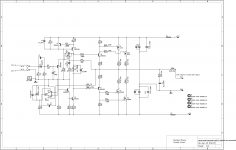 sch_2.2.1_rec2.png29.8 KB · Views: 2,554
 -
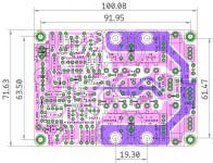 lay 2.2.1.png111.5 KB · Views: 2,152

That is a beautiful pcb Prasi! You really are a pro now.........
Marc, very nice work, elegant!
Hugh
Marc, very nice work, elegant!
Hugh
Thank you Hugh 🙂
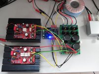
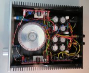
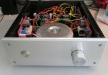
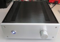
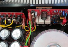
And now the finished amplifier built with the help of Philippe for mechanical and wiring 😀
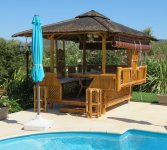
It will replace the Quasi for driving outside speaker for musical dinner and cocktail in the bamboo dinning house

Ciao,
Marc
And now the finished amplifier built with the help of Philippe for mechanical and wiring 😀
It will replace the Quasi for driving outside speaker for musical dinner and cocktail in the bamboo dinning house
Ciao,
Marc
Attachments
Hello Hugh,
Thank you very much for your kind words.
Hello Marc,
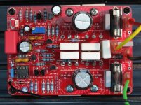
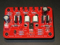
Thats a very compact and very nice build. Is it a SS relay protect PCB?
Enjoy the cocktail dinner with your new musical amplifier!
regards
Prasi
Thank you very much for your kind words.
Hello Marc,
Thats a very compact and very nice build. Is it a SS relay protect PCB?
Enjoy the cocktail dinner with your new musical amplifier!
regards
Prasi
Thanks Marc,
One more thing, don't forget to fit a 5-6 uH inductor inline with output ... It's called for by the designer Mr. Karl Mooly
Regards
Prasi
One more thing, don't forget to fit a 5-6 uH inductor inline with output ... It's called for by the designer Mr. Karl Mooly
Regards
Prasi
mooly amp
Hi Mooly: You where correct about construction errors. At the moment I have 1.2V across R8 and .5 across R5. At the base of Q6 I have 2V to ground, at the base of Q7 I have .28V to ground and .4 at the output to ground. Could you advise please.
Thanks. Richard
Hi Mooly: You where correct about construction errors. At the moment I have 1.2V across R8 and .5 across R5. At the base of Q6 I have 2V to ground, at the base of Q7 I have .28V to ground and .4 at the output to ground. Could you advise please.
Thanks. Richard
Dear Mooly,
I have the PCBs laid out by Prasi and got made by e_fortier.
I have the following transistors procured from Mouser. KSC3503D, KSA1381E, KSA1220AYS, KSC2690AYS, KSA992FTA, KSC1845FTA, & BC546C. (Yes-C) I have 5551 & 5401 of unknown quality. Which of those transistors can I use in which place ? As per the drawing in post 719 of Prasi? I shall be using transformer 25-0-25 or 30-0-30 V AC. I also have 546B/556B, 560C/550C, from Fairchild.
I understand that the pin orientation is to be changed.
Thanking you,
--gannaji.
Hi Mooly: You where correct about construction errors. At the moment I have 1.2V across R8 and .5 across R5. At the base of Q6 I have 2V to ground, at the base of Q7 I have .28V to ground and .4 at the output to ground. Could you advise please.
Thanks. Richard
The voltages on R5 and R8 are in the right zone.
I would check around the opamp. Make sure the supply voltage is correct as measured on pin 4. It should be negative 12 volts. The opamp output pin should be approximately negative 5.5 volts.
Make sure the opamp is a genuine TL071.
If you are running on a lower supply rail than the original -/+45 volts then you will need to decrease R27 which is a 10k feeding the negative supply to the opamp.
Dear Mooly,
I have the PCBs laid out by Prasi and got made by e_fortier.
I have the following transistors procured from Mouser. KSC3503D, KSA1381E, KSA1220AYS, KSC2690AYS, KSA992FTA, KSC1845FTA, & BC546C. (Yes-C) I have 5551 & 5401 of unknown quality. Which of those transistors can I use in which place ? As per the drawing in post 719 of Prasi? I shall be using transformer 25-0-25 or 30-0-30 V AC. I also have 546B/556B, 560C/550C, from Fairchild.
I understand that the pin orientation is to be changed.
Thanking you,
--gannaji.
You could try the KSC3503D for Q5 the VAS, and the KSA1220 for Q3 which is the current source.
Q2 can be a BC560
Q1 could be a BC560 as long as the supplies are not to high. It will see a voltage just a little less than the negative rail under all drive conditions. It is a -50 volt device.
The same applies to Q4 although this is NPN (BC550)
Q6 and Q7 need to withstand the full combined supply and so could be either the KSC3503D and KSA1381E or the KSC2690AYS and KSA1220AYS.
All these are untried substitutions however and so no guarantees are possible that will perform without issue. You will have to look up the data sheets for each one to determine the correct pinout.
mooly amp
I have + - 33volts any suggestions for the 10 k resistor?( ex pat from orpington kent and lifelong devotee of linsly hood)
I have + - 33volts any suggestions for the 10 k resistor?( ex pat from orpington kent and lifelong devotee of linsly hood)
- Home
- Amplifiers
- Solid State
- My MOSFET amplifier designed for music