OK I found on post 425 that I have to set the trimmer at 500 ohms (maximum on clock direction before to measure the current while I reduce the value of the trimmer 🙂
Not exactly... that post was in response to another and says to use to use a 470 to 1k trimmer, not to set it at that. You need to start with the preset on minimum resistance to give an initial minimum bias current.
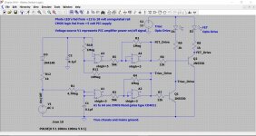
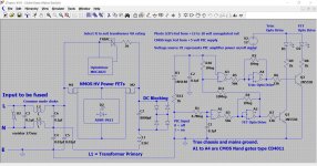
A question to Mooly. In post 1 schematic, for 2SJ162, pin 3 is shown as source, whereas pin 2 is source😕. I have attached post 1 schema for convenience.
That diagram was drawn using Diptrace PCB software (it was done way before I got into using LTspice) and was simply a way to get a neat drawing configured.
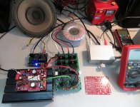
Every things is connected, I am using a 100 W 8 ohms power resistor as a load and I have a 2 x 22 V AC toroidal power transformer connected through a Variac to control power voltage !
I have used 5 A fuses (they are not specified on the BOM, but I see that value on a PCB serigraph ?) and I made a short circuit on the input...
I still have some questions :
- Can I run the amplifier from 0 V to 30 V or should I start immediately with the Variac a the main level that will give about 30 V DC ?
- How should I adjust the bias trimmer at the power up ? And if I read correctly in the thread I should adjust it until I have 23 mV on one of the 0,22 ohms output emitter resistor 😕
I hope I get your recommendation before I destroy this nice amplifier 🙄
Thanks,
Marc
1. 5A fuse is ok.
2. 100mA bias is ok for lateral mosfet. bias measured across drain to drain voltage drop of 45mV (I=45mV/0.44ohms=100mA)
3. inline Rail resistors of 10- 22ohms (2-3watts) could be useful here and voltage drop across them would convey the correctness of build as you bring up the variac voltage. the circuit shouldnt consume more that ~200mA , this translates to 2V drop across the 10ohm inline resistor.
regards
Prasi
Last edited:
That diagram was drawn using Diptrace PCB software (it was done way before I got into using LTspice) and was simply a way to get a neat drawing configured.
ok, got it.
I hear the music...
Thanks Mooly 🙂
That was the problem, when I powered the amplifier with the trimmer on 500 ohm the bias was far too high and I didn't see it because my ANENG multimeter didn't work properly 🙁
Now I tested again starting with the trimmer at 0 ohm and the resistors didn't became hot but I could not adjust the bias and I found the multimeter problem therefor I take an other one and I could adjust the bias at 22mV on one 0.22 ohms resistor 🙂
I also checked the offset correction and found -4.895 V DC and 0 mV on speaker output ! Now I am running the amplifier with +/- 28 V DC power supply
Next step : I will increase the power supply and test the amplifier with a better speaker before to build the second channel...
I cannot comment on the sound yet because it is a very basic old speaker without cabinet used for my initial tests in case of dramatic failure 😉
I am still a little bit suspicious about the MOSFET because they look so new for obsolete product ?
Best regards,
Marc
Attachments
I had 2 pair Renesans mosfet like exact yours from a reliable source. Based on your picture I really believe those are real parts. Also, you mentioned you purchased those from Reichel. That is a good source, I do not believe they sell fake semis. I did order BDW Darlington transistors and they were real.
Offset at the output terminal should always be very close to zero, however 28 volt rails are quite low and so the 10k feed to the Zener may need reducing in value to maintain a negative 12 volt rail for the opamp.
Fake or real lateral mosfet
I suppose it would be unlikely to have someone able to sell fake working lateral mosfet because of their specific characteristics such as temperature coefficient, low gate voltage threshold compared to other vertical mosfet. With such a schematics meant for lateral mosfet and without thermal compensation using vbe transistor (or else) your amp would probably be in thermal runaway after some time following power up... if you have < 1,5v gate voltage to obtain 100ma bias current then it matches lateral mosfet expected vgs.
Fab
Last edited:
Hello Marc,
I always use a mains bulb tester(MBT) while testing a new circuit or any changes have been made in wiring or components. It immediately gives me a visual indication of shorts or over current consumption without making anything hot or smoky.
If MBT bulb doesnt light up on initial power up, it shows there is no shorts or bias is minimal.
While the bias pot is being adjusted if one is able to control the brightness of bulb gradually, it means bias circuit is working properly and there is no oscillation. if bulb goes from off to full bright, there could be oscillation. Just as a visual indication.
Use of MBT was routinely advised by former member AndrewT (RIP).
I even run my amps on test speakers with MBT connected for following
1. to listen for any hum/hiss
2. at very low volume for some time atleast until I get confidence that amp is ok and while checking if any small signal tranny is overheating , monitor zobel resistor, etc.
regards
Prasi
@ Bandol
where do you buy your k1058 and j162 ?
I know very well these complementary, I used them regularly from 1998 and my first Plantefeve and it's been a long time since I've seen authentic for sale on the net.
the last, I bought them from Renesas and they were all perfect and still work on two of my amps for years.
otherwise, if in doubt, buy a C-audio st600 amp or even a st400, and strip the mosfets
https://www.renesas.com/in/en/doc/products/transistor/003/rej03g0906_2sk1056ds.pdf
Hi Mooly, fab and gaborbela,
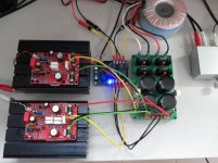
I am back on the amplifier after a (too) long lunch break 🙂 As I planned, I have removed the Variac and connected the amplifier directly to the main voltage (about 240 V here) and I have now +/- 31.2 V DC on the amplifier, I have a 300 VA 2 x 22 V AC transformer !
I can use an other one 300 VA 2 x 35 V AC but it will give nearly 50 V DC, is it acceptable ?
Currently the Vbias measured on R23 is stable at 23 mV and Voffset at pin 6 of the TL071 is -4.82 V and I also measured Vgs = 0.81 V as suggested by fab, this and the comments of gaborbela give me more confidence in Reichelt parts 🙂
I have some background noise but it is probably due to the very bad wiring of the ground lines, I had also this problem at the beginning with the quasi but after a good assembly it was dead silent !
Cheers,
Marc
Still4given, had pretty hot Q3/Q5 at +/-45V. here is the post My MOSFET amplifier designed for music.
you can use 50V, however you may need to monitor the temperature and may need to fit some sort of clip on heat sink for Q3/5 as suggested by Mooly in post #500 or use to-126 parts.
you can use 50V, however you may need to monitor the temperature and may need to fit some sort of clip on heat sink for Q3/5 as suggested by Mooly in post #500 or use to-126 parts.
Good to hear you have it working Marc.
The negative voltage on the TL071 output is normal and that is not the offset voltage of the main amp but simply the DC bias voltage needed to bring the main amp offset to zero.
With -/+45 volt rails you would see around -6 volts on the opamp output, so a little lower for lower voltage rails.
The negative voltage on the TL071 output is normal and that is not the offset voltage of the main amp but simply the DC bias voltage needed to bring the main amp offset to zero.
With -/+45 volt rails you would see around -6 volts on the opamp output, so a little lower for lower voltage rails.
Thanks Mooly, your comments about the bias trimmer that should be at the minimum to start to measure the bias current saved me 😀
In fact, with this error avoided, the amplifier will have played immediately and I should also say to Prasi (since it seems that I am the first one to build it on this PCB) that even if it is very compact there was absolutely no problem to build it 🙂
As I have said, I only listen it on an old test speaker and if I cannot yet give useful comments about the sound but I can already tell you that it has a lot of "punch" even with only 31 V power lines...
Need to buy some components like the 5 W resistors to finish the second channel 🙁
Bye,
Marc
More over it's tweaked by AKSA, so as a tube lover I am sure you will like the sound.
I didn't pay attention but I think I knew what AKSA was suggesting (addition of a resistor) and I believed it will solve the weakness of this amplifier. But DaveS in the end thought that he prefer the original schematic, saying that the mod had more details but analytic or something like that. I'm curious but always forget to check what's going on...
mooly amp
Hi karl do you have a soft turn on circuit for your amp or any other for that matter cheers. ampman.
Hi karl do you have a soft turn on circuit for your amp or any other for that matter cheers. ampman.
The second channel is playing music
Now i can listen the music in stereo
I have built the second channel with only one pair of output transistors and I cannot hear a difference with the left channel which use two pairs 😕
I didn't mount the 680k resistor and I found that the sound is clearer without it, in a certain way it is less tube like 😀 If I compare with the Quasi, I found that both are very close, but I was very surprised by the sound of the Quasi because it was a new experience for me and now as I become more knowledgeable with transistor amplifier I am always expecting more
I am now listening on small bookshelves Yamaha speaker and I like the result but I will try with my Alon "Petites" to have a better feeling of the amplifier qualities...
Now I will start to build the Hybrid amplifier, I will make a new thread in the tubes forum 😉
Cheers,
Marc
Attachments
Hi karl do you have a soft turn on circuit for your amp or any other for that matter cheers. ampman.
Non of the amps I've built (and none of the commercial ones I've owned) have had a soft start circuit.
Thats not to say they are not a good idea in some cases, but they do seem to have become a bit of a 'must have' accessory in recent years.
My favoured soft start method is a triac for the initial power on inrush that then gets bypassed with a very low resistance FET power switch. The FET turns on after the triac has operated and off before the triac is turned off.
Attachments
Hello Marc,
The double output pairs is simply meant to handle more power (with higher voltage) and higher reliability.
Those Alon speakers would sure to reveal more details/ differences I am sure.
regards
Prasi
The double output pairs is simply meant to handle more power (with higher voltage) and higher reliability.
Those Alon speakers would sure to reveal more details/ differences I am sure.
regards
Prasi
- Home
- Amplifiers
- Solid State
- My MOSFET amplifier designed for music