very impressive, Bimo! Very low THD, congratulations........
BUT, it is not the THD which is remarkable. It is the monotonic decrease which impresses. Straight line, linear. An accomplished amplifier!
HTF did you do this? I think John Curl would be very impressed with this too. Not to mention NP. Perhaps you should ask Pass Labs for a job!
HD (high distortion)
It is only simulation 🙂 a symmetrical topology with OITPC compensation by Dadod which I modify slightly. But I tried this compensation on CFA topology and Emprit amplifier and succeeded. All built by my friends.
This compensation produce monotonic harmonic, sometime until 20kHz depend on the topology. I still learn it.
Bimo, I see that you use different DC servo in your LTSpice file. Have you observed audibility between low noise opamps and high noise ones like the TL071 used in the original cct?
I used TL072 and sometime LF411. But I rare used DC Servo. Maybe next time I will compare them in same amplifier. I design discrete op-amp for DC Servo, too. But not implemented yet, only in simulation.
I design discrete op-amp for DC Servo, too.
You wont take the hassle if you knew there would be no improvement to the cheap TL072 option, will you?
Every DIYers have so many unused opamps in his drawers, so we can consider that using opamp is very cheap.
You wont take the hassle if you knew there would be no improvement to the cheap TL072 option, will you?
Every DIYers have so many unused opamps in his drawers, so we can consider that using opamp is very cheap.
Of course 🙂 But for prototype I need to try cheap components first. If the design work as expected, then tweak to use better components.
Ah, BB, very droll........
I think it is a reference to 90% of the SS amplifiers in the marketplace which were not necessarily designed for music, but rather for low THD.
Study the design. It is different to most, and there are tricks in it which are interesting. The amp is designed for a monotonic declining harmonic.
HD
Droll?
I use similar simple topology in my amp, monotonic decline harmonics sound better with simple music, so I have a switch for various harmonic content...😉
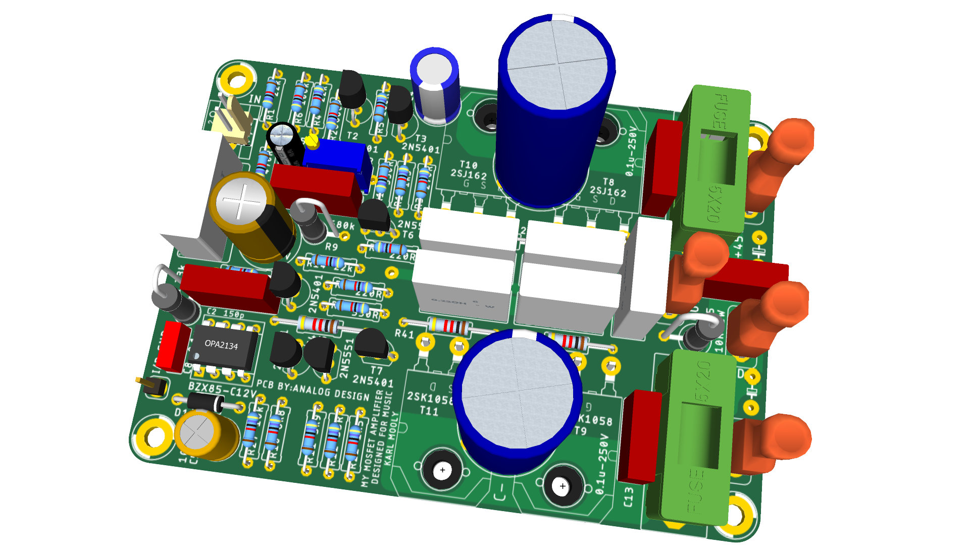
Is there any possibility of getting the gerber files for this version with four outputs? Just for home-use of course!I admit it Prasi, I am having wandering amp eyes again, and that is is a fine looking board - bravo!
Makes me want to build it too after seeing the 3d renders! Using 4 latFETs (especially, discontinued ones) makes this a tough sell for me, personally though.
Beautiful to look at nonetheless...
Congrats on an excellent looking layout.
Hi Prasi,
Same here, had a small batch of the single pair mosfet boards made up, but have not assembled one yet. 🙄
Same here, had a small batch of the single pair mosfet boards made up, but have not assembled one yet. 🙄
Hi Prasi,
It seems that I will be the first to test your PCB
Thank you for the Gerber files, but I didn't get the boards from PCBWay yet since they were blocked for more than 3 weeks in Beijing due to very bad work of E-packet 😡 Hopefully in the mean time I have received a set from Eric
My friend Philippe is coming this afternoon with two drilled heat sinks and we will start test soon No, the test first and drink if it work 😀
Thanks again Prasi and Eric four your regular support
Marc
It seems that I will be the first to test your PCB
Thank you for the Gerber files, but I didn't get the boards from PCBWay yet since they were blocked for more than 3 weeks in Beijing due to very bad work of E-packet 😡 Hopefully in the mean time I have received a set from Eric
My friend Philippe is coming this afternoon with two drilled heat sinks and we will start test soon
No, the test first and drink if it work 😀Thanks again Prasi and Eric four your regular support
Marc
Attachments
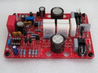
Wow! Looks perfect , congrats on a nice build. Looks almost facsimile of the 3d model I posted!☺️ and I am sure it will work flawlessly too. More over it's tweaked by AKSA, so as a tube lover I am sure you will like the sound.
And yes! Drink later once you test.
Let me know, I will pOp a beer can here too😉. Summer is here and temperatures are soaring to 40 deg. C. :Hot:
Regards
Prasi
And yes! Drink later once you test.
Let me know, I will pOp a beer can here too😉. Summer is here and temperatures are soaring to 40 deg. C. :Hot:
Regards
Prasi
One thing, hope you are aware... The input ground has be connected separately by wire to clean side of PSU ground. Also op amp should be TL071.
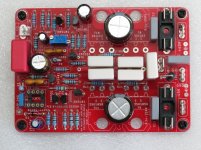
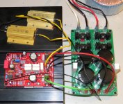
Finally we have finished the assembly of the Mooly amplifier but we didn't started the test yet because we still had some work on the tube preamplifier with RIAA stage and remote control that is the companion of the EL34 Baby Huey as you can see on the picture of Philippe 😀
Tomorrow will be an other day and I will start the test fully relaxed 😴 But we had already a drink anyway 🙂
For info, I finally received the boards from PCBWay, it was a long wait but at the end they made the effort to send them again by DHL "free of charge", more detail later on the quasi complementary thread 🙂
Best regards,
Marc
Attachments
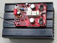


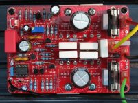
Ready for power up !
Every things is connected, I am using a 100 W 8 ohms power resistor as a load and I have a 2 x 22 V AC toroidal power transformer connected through a Variac to control power voltage !
I have used 5 A fuses (they are not specified on the BOM, but I see that value on a PCB serigraph ?) and I made a short circuit on the input...
I still have some questions :
- Can I run the amplifier from 0 V to 30 V or should I start immediately with the Variac a the main level that will give about 30 V DC ?
- How should I adjust the bias trimmer at the power up ? And if I read correctly in the thread I should adjust it until I have 23 mV on one of the 0,22 ohms output emitter resistor 😕
I hope I get your recommendation before I destroy this nice amplifier 🙄
Thanks,
Marc
Attachments

OK I found on post 425 that I have to set the trimmer at 500 ohms (maximum on clock direction before to measure the current while I reduce the value of the trimmer 🙂
It does not work !
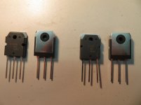
I started the test with 20 VDC power supply and immediately the 0.22 ohm resistors and the output transistors became very hot, I could smell the heat and I stopped very quickly... I had the time to check the output of op amp at about 4.7 V, but surprisingly the voltage on one emitter resistance was 0 V ?
Something look very strange to me and I am wondering if the trasistors are genuine ? I bought from Reichelt MOSFETs (transistors a effet de champ a semi-conducteurs a oxyde metallique) chez reichelt elektronik Could they be fake ?
I will stop the test for today 😡
I don't want to have such high power dissipation until I found the reason, I will check the board again...
Rgds,
Marc
Attachments
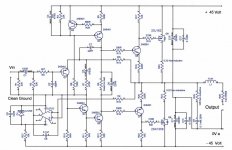
Hello Marc,
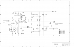
Thats bad luck on first power. Here is the schematic again.
I would suggest the following as a trouble shoot.
1. please check your small signal transistors for correct types (NPN /PNP) in correct places.
2. Testing mosfets.
Here is a quote from Shaan suggested by him to me during my PEECEBEE amp build.
"To test the MOSFETs you need a piece of wire and a multimeter. For the N MOSFET set your meter in diode test mode and connect the red probe to pin 3 (drain) and black probe to pin 2 (source). Now short pin 1 and 2 with the wire and the meter should show open circuit. Short pin 1 and 3 and the meter should show around a couple hundred or less. If you get both true then the MOSFETs are good. To check the P MOSFET reverse probe polarity and short the same pins as mentioned above with the wire."
hope you get to the bottom of this and solve it soon.
regards
Prasi
A question to Mooly. In post 1 schematic, for 2SJ162, pin 3 is shown as source, whereas pin 2 is source😕. I have attached post 1 schema for convenience.
Attachments
Last edited:
- Home
- Amplifiers
- Solid State
- My MOSFET amplifier designed for music