Gunni,
probably because you have changed number of posts per page settings in your user control panel... just a guess.
regards
Prasi
probably because you have changed number of posts per page settings in your user control panel... just a guess.
regards
Prasi
I cant remember if I posted them, here they are.
regards
Prasi
Hello Prasi
This seems to be a good amp. Where can i find more details on this amp.
Thanks.
Hello viki,
Post 1 provides all details. It's same amp.
There is also a spice file posted by designer.
Also there are some build reviews.
Regards
Prasi
Post 1 provides all details. It's same amp.
There is also a spice file posted by designer.
Also there are some build reviews.
Regards
Prasi
Hello Prasi,Gunni,
probably because you have changed number of posts per page settings in your user control panel... just a guess.
regards
Prasi
usually the number of the post is unique, as a home address. maybe depends on the browser, because when checking the link from page 1 and the link of the post number i get different content of the link.
Nevertheless i got my both pcb working with voltage at the drain resistors of 26mV (Iq about 120mA) and 0,8mV output offset. Next willbe a sound check and completing the mechanics.
i know it will sound very good, thanks to Mooly
BR
Günni
PS: one or two Mosfets, what is the advantage or disadvantage at rail voltage of +/-45V?
Two pairs of FET's would allow better current delivery into adverse loads at high output levels, however the single pair have proved more than adequate for my B&W703's which dip down to around 3 ohms on the impedance curve.
mooly amp
hi mooly I have 12volts at the input of 71 and can only get .87 at the output I'm stumped. I have built two amps and I'm very pleased with the sound, I built JLH and I can't tell the difference. thx richard
hi mooly I have 12volts at the input of 71 and can only get .87 at the output I'm stumped. I have built two amps and I'm very pleased with the sound, I built JLH and I can't tell the difference. thx richard
Do you mean negative 12 volts supply on pin 4 of the TL071? and 0.87 volts at the speaker output.
If so then the output of the opamp (pin 6) should be around negative 6 volts. The opamp must be a genuine TL071, do not substitute it with any other type.
If so then the output of the opamp (pin 6) should be around negative 6 volts. The opamp must be a genuine TL071, do not substitute it with any other type.
mooly amp
Hi moolyI have 12 volts at p4 .87 at p6 and 32 volts at amp output, Ihave swapped the 71 from my working amp with the same result?
Hi moolyI have 12 volts at p4 .87 at p6 and 32 volts at amp output, Ihave swapped the 71 from my working amp with the same result?
You have to be specific 🙂 the devil is in the detail and you haven't indicated if any of those three voltages are negative in polarity.
I'm assuming the 12 is really -12 and that the 0.87 is really -0.87. If that is so then something is very wrong around the IC. If you have plus 0.87 at the opamp output then something is pulling that point positive.
Is the input coupling cap fitted with correct polarity. Remember the negative end goes to the edit... transistor base side, positive end to the audio input.
Also make sure the feedback cap is fitted correctly, positive end to ground.
What polarity is the 32 volts with respect to ground. I'm assuming its positive but can you confirm this.
Pin 3 of the opamp should be at 0 volts (ground). Check that the 1 meg goes from pin 2 to the main amp output.
mooly amp
I h ve checked all caps and tracks q1 and q4 are to hot to touch output to pos is 62 to neg iss2.7
I h ve checked all caps and tracks q1 and q4 are to hot to touch output to pos is 62 to neg iss2.7
Concentrate on Q1 and look at the circuit.
There is no low impedance path that could pass enough current to overheat Q1. There is the 22k feedback resistor and the combined 4k7 and 33k that connect to the base.
If Q1 is very hot then there must be a short or solder blob somewhere, or the PCB layout is incorrect somehow.
You say you have already built two that work... so something has gone very astray with these latest builds.
Also check that the transistors are what they say they are. Fake parts can even be of the wrong polarity NPN for PNP and vice versa... check all possibilities.
I h ve checked all caps and tracks q1 and q4 are to hot to touch output to pos is 62 to neg iss2.7
Hello Ampman,
You could run the spice file posted by Mooly and see the various voltages in your build and compare.
That will give you an idea. or post the diagram showing your voltages, that will be of help to designer to identify the problem.
Concentrate on Q1 and look at the circuit.
There is no low impedance path that could pass enough current to overheat Q1. There is the 22k feedback resistor and the combined 4k7 and 33k that connect to the base.
If Q1 is very hot then there must be a short or solder blob somewhere, or the PCB layout is incorrect somehow.
You say you have already built two that work... so something has gone very astray with these latest builds.
oh nooo I was about to order a few PCB's is there actually an errata on the layout?
PCB layout is incorrect somehow.
Mosfet Amplifier designed for music
Hello Mooly
greetings i would like to try your amplifier as i have all parts
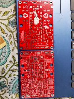
and orignal mosfets i would like to etch the pcb at home is this the
correct pcb layout please can you confirm
warm regards
Andrew😕
Hello Mooly
greetings i would like to try your amplifier as i have all parts
and orignal mosfets i would like to etch the pcb at home is this the
correct pcb layout please can you confirm
warm regards
Andrew😕
I suspect you’ll need to be more specific. There are several pcb layouts presented in this thread. Which post are you referencing?
oh nooo I was about to order a few PCB's is there actually an errata on the layout?
PCB layout is incorrect somehow.
I never actually produced any boards for this amp (not for the forum anyway) as the amp was designed and built before I got into using a PC for circuit design and layouts.
Hello Mooly
greetings i would like to try your amplifier as i have all parts
and orignal mosfets i would like to etch the pcb at home is this the
correct pcb layout please can you confirm
warm regards
Andrew😕
AFAIK the boards offered by Prasi are fine and several members have built the amp with no issues. AMPMAN has also built two of these amps with no issues as far as we know as he says.
Extract:
...............I have built two amps and I'm very pleased with the sound..................
I suspect you’ll need to be more specific. There are several pcb layouts presented in this thread. Which post are you referencing?
Exactly. The design is proven and as far as I know, so are the boards produced by Prasi.
Hello Ampman,
You could run the spice file posted by Mooly and see the various voltages in your build and compare.
That will give you an idea. or post the diagram showing your voltages, that will be of help to designer to identify the problem.
This shows typical voltages at key points in the circuit.
(This is an old file and the component reference numbers probably don't match your PCB... so work from the circuit itself. Remember that voltages that are referenced to a rail will vary, however you are looking for the correct voltage difference such as 0.6 volts across the 100 ohm)
Attachments
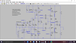
I've just replaced the image above for 'technical reasons' 😉 with LTspice.
I snipped a voltage source after running the sim and it changed the voltages already tagged... that's obviously an LT thing as I hadn't run the sim again.
The real amp has NO positive supply to the opamp, whereas the sim needs one.
I snipped a voltage source after running the sim and it changed the voltages already tagged... that's obviously an LT thing as I hadn't run the sim again.
The real amp has NO positive supply to the opamp, whereas the sim needs one.
AFAIK the boards offered by Prasi are fine and several members have built the amp with no issues. AMPMAN has also built two of these amps with no issues as far as we know as he says.
The design is proven and as far as I know, so are the boards produced by Prasi.
Actually I just designed the PCB and posted the gerbers🙂, bandol83 (Marc) + some others got them produced.
Marc has kindly donated a couple of PCBs to me😎. I am keeping them for my build at leisure.😛
regards
prasi
Attachments
- Home
- Amplifiers
- Solid State
- My MOSFET amplifier designed for music