An slightly different approach to what's being discussed on this thread.
There's an ongoing thread over the JC-2 line preamp here:
http://www.diyaudio.com/forums/solid-state/120243-variation-jc-2-preamplifier-25.html#post2884005
But on post #358 of this thread there's the complete circuit of the preamp, involving several external parts. What I wonder is whether they should be included or not on this project.
For instance, there's the Output Amp, which I guess is the JC-2 Line Amp, but there is an external NFB (C18/2uF; R33/2K; R34/4K53; Balance Switch) which I think is very important. There's also a Volume Pot (VR4/10K) and a switchable output coupling capacitor (2uF).
From what I see, apparently Jim's Audio and Tubeshunter kits do not include any of these parts, even if there is space for an unspecified volume pot.
Should these parts be included or not?
jfets availability
hi all,
I would like to try the JC-2 line preamplifier, I find the schematic very clever and interesting and there are rumors around that it is performing very well! 😎
But.... the jfet availability is giving me some problems. Reading the previous comments in this thread, I assume that the input Jfets have to be used with at least 10mA in order to have the best sound.
I have been able to find only 2SK170/2SJ74-GR or 2SK246/2SJ103-BL.
The 2SK170/2SJ74-GR can be matched at about 5.7mA, the 2SK246/2SJ103-BL at about 10mA
Which is the best choice?
Basically higher Idss is better, I would go for the 2SK246/2SJ103-BL.
You would need to increase R2, R3 from 150 Ohms to about 191 Ohms and adjust
the bias pot for about 1.3V accross each of them.
The bipolars (Sanyo 2SA1209 / 2SC2911) can be substituted by Fairchild 2SA1381 / 2SC3503.
You would need to increase R2, R3 from 150 Ohms to about 191 Ohms and adjust
the bias pot for about 1.3V accross each of them.
The bipolars (Sanyo 2SA1209 / 2SC2911) can be substituted by Fairchild 2SA1381 / 2SC3503.
Hi Georg,
thank you for your answer.
The 2SK246/2SJ103 combination should present also a lower input capacitance allowing then to use a higher value for the input potentiometer, right?
I already have the 2SA1209 and 2SC2911, do the 2SA1381/2SC3503 perform better?
Thanks!
Ciao
Paolo
thank you for your answer.
The 2SK246/2SJ103 combination should present also a lower input capacitance allowing then to use a higher value for the input potentiometer, right?
I already have the 2SA1209 and 2SC2911, do the 2SA1381/2SC3503 perform better?
Thanks!
Ciao
Paolo
Basically higher Idss is better, I would go for the 2SK246/2SJ103-BL.
You would need to increase R2, R3 from 150 Ohms to about 191 Ohms and adjust
the bias pot for about 1.3V accross each of them.
The bipolars (Sanyo 2SA1209 / 2SC2911) can be substituted by Fairchild 2SA1381 / 2SC3503.
Hi Andrew,
are you meaning that only the V (or at least BL) version of the 2SK170/2SJ74 is suitable for this application?
Do you maybe know about other possible replacements?
Thank you,
Paolo
are you meaning that only the V (or at least BL) version of the 2SK170/2SJ74 is suitable for this application?
Do you maybe know about other possible replacements?
Thank you,
Paolo
neither.
...
The 2SK246/2SJ103 combination should present also a lower input capacitance allowing then to use a higher value for the input potentiometer, right?
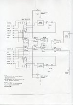
I would not go above 50k with the potentiometer anyway. Attached is the
block diagram of the JC-2 / ML-1, 10k potentiometer with 20k before it (in the
"low" gain position). You could use a potentiometer in the 20k - 30k range (without the the high / low switch).
...
I already have the 2SA1209 and 2SC2911, do the 2SA1381/2SC3503 perform better?
No they don´t perform better (I use 2SA1209 and 2SC2911 myself) but the 2SA1381/2SC3503 are more readily available (at Mouser for example).
Attachments
They changed the process for these fets, they are not low noise like they
used to be 40 years ago. To quote John Curl: "I found that Siliconix J110's , that I originally spec'd for the JC-2, over 35 years ago,
got VERY noisy in the late 70's, and remain so today, because they switched to ion implantation."
the 246/103 is not a good replacement for the 170/74Hi Andrew,
are you meaning that only the V (or at least BL) version of the 2SK170/2SJ74 is suitable for this application?
Do you maybe know about other possible replacements?
Thank you,
Paolo
I think the specified grade for the 170/74 is BL. GR is too low Idss and that limits the gain and transconductance.
...... Attached is the block diagram of the JC-2 / ML-1
thank you Georg!!! I was missing this schematic!
...and then another question arise: if I don't use the balance switch, should I use the resistor combination of the "zero" position?
10k potentiometer with 20k before it (in the "low" gain position). You could use a potentiometer in the 20k - 30k range (without the the high / low switch).
ok, I see the point now.
No they don´t perform better (I use 2SA1209 and 2SC2911 myself) but the 2SA1381/2SC3503 are more readily available (at Mouser for example).
perfect, I will stay with the 2SA1209 and 2SC2911 then!
Thanks!
Paolo
Hi Andrew,
then the right question should be: which is the most similar device respect to the original one, 212/75? Considering a 170 with the same Idss of a 246, from datasheet the first has a gm of 22 and the second of 9. The J212 datasheet (at least the one that is available now) says a gm of 12.
Where am I wrong (and sure I am 🙂 )?
the 246/103 is not a good replacement for the 170/74
I think the specified grade for the 170/74 is BL. GR is too low Idss and that limits the gain and transconductance.
I just had a look at FET Audio | Hi-End Audio Projects (Spencer is a member here),
an they still have 2SJ74 / 2SK170 matched in BL grade.
Spencer even has matched quads (quote: "Maximum match is 4 pcs K170 and 4 pcs J74 with same idss match together in one group.")
Matched quads is what I used with good results for my build.
an they still have 2SJ74 / 2SK170 matched in BL grade.
Spencer even has matched quads (quote: "Maximum match is 4 pcs K170 and 4 pcs J74 with same idss match together in one group.")
Matched quads is what I used with good results for my build.
...and then another question arise: if I don't use the balance switch, should I use the resistor combination of the "zero" position?
...
If you combine all resistors in the feedback loop (at the "zero" position) you
get 21.3 kOhms. With the 2kOhms to ground this is 21 dB gain.
If this suits your needs depends on the voltage gain of your power amplifier.
Personally I have never needed to use the "high" position on my ML-1 ("low"
attenuates by approx. -10dB this results in a total gain of 11dB).
I don't need a lot of gain, I think that 10dB is plenty.
I am wondering now if it is better to use the "low" gain setting (attenuating the input) and a "zero position setting" (or "higher feedback setting") of the feedback or a zero attenuation and a "higher feedback setting"......
Am I worring too much? 😀
Thank you Georg
I am wondering now if it is better to use the "low" gain setting (attenuating the input) and a "zero position setting" (or "higher feedback setting") of the feedback or a zero attenuation and a "higher feedback setting"......
Am I worring too much? 😀
Thank you Georg
If you combine all resistors in the feedback loop (at the "zero" position) you
get 21.3 kOhms. With the 2kOhms to ground this is 21 dB gain.
If this suits your needs depends on the voltage gain of your power amplifier.
Personally I have never needed to use the "high" position on my ML-1 ("low"
attenuates by approx. -10dB this results in a total gain of 11dB).
5.6mA is the highest Idss for a quad match I can reach. Is it too low or it is worth trying?
Thanks,
Paolo
Thanks,
Paolo
The highest Idss pair of 170/74 GR you can get.
5.6mA is the highest Idss for a quad match I can reach. Is it too low or it is worth trying?
5.6mA seems rather low to me, this is 1/3 of the "V" parts I use. I would not
cheap out on these parts and order them form Spencer ("BL" grade), as long as
he still has 2SJ74 available, and ask for the highest Idss matched quads he
can offer (should be around 10mA or so).
I don't need a lot of gain, I think that 10dB is plenty.
I am wondering now if it is better to use the "low" gain setting (attenuating the input) and a "zero position setting" (or "higher feedback setting") of the feedback or a zero attenuation and a "higher feedback setting"...
I can confirm that the "-4dB" setting (this is 17dB gain from the line stage) is
stable; how much feedback you can apply to lower the gain without stability problems
I don´t know. (I would estimate that the gain has to be > 3 at least).
- Home
- Source & Line
- Analog Line Level
- Need to build JC 2 preamp