Looks good. What you have now is almost the ORIGINAL JC-2 phono stage. The only real difference is that we SHARED the cap multiplier, but that was NOT GOOD. Better to have SEPARATE cap multipliers for each channel.
Yes, I´ve read carefully what you already wrote about the cap multiplier in the JC-2 here and in other threads. ;-) I´ll try to summarize all points tomorrow for the readers of this thread.
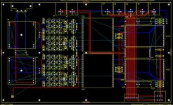
I´ll try to fit the separate multipliers direct on the new phono pcbs (If I can - they are 1.5 x 2.0 inch only). (Probably I make them bigger and use some of the space which originally was reserved for the MC pre.)
I´ll try to fit the separate multipliers direct on the new phono pcbs (If I can - they are 1.5 x 2.0 inch only). (Probably I make them bigger and use some of the space which originally was reserved for the MC pre.)
Hi John,
I'm sorry to hear about that. I've had enough of the same thing myself. It's frustrating.
I only commented because it appeared that you couldn't post it on this site, specifically.
You might want to try one of those external hard drive things so you won't lose anything. You can get them to plug in a USB port, or an Ethernet port. That way you could access the information with a replacement computer if you had to.
Hi gk7,

I have some schematics on file for this unit, but I wouldn't post anything without John's approval. If nothing else, I have many, many files and I can even find the odd one.
-Chris 😀
I'm sorry to hear about that. I've had enough of the same thing myself. It's frustrating.
I only commented because it appeared that you couldn't post it on this site, specifically.
You might want to try one of those external hard drive things so you won't lose anything. You can get them to plug in a USB port, or an Ethernet port. That way you could access the information with a replacement computer if you had to.
Hi gk7,
I'm sorry. That's far too complicated for me to figure out by myself.Well, a capacitor multiplier consisting of one transistor, one cap and one resistor per supply rail should be easy enough to figure out without a schematic, no ?
I have some schematics on file for this unit, but I wouldn't post anything without John's approval. If nothing else, I have many, many files and I can even find the odd one.
-Chris 😀
By john curl - Better to have SEPARATE cap multipliers for each channel.
Not only that , but why not "splurge" on another R/C and make it 2'nd order (R/C/R/C). This will even tame 3V+ ripple on a power amp's rails down to 5-10mv. Also use highest gain N/P devices to get the largest multiplication factor.
I use 2sa1381/2sc3503{Y grade} , perfect for this app, project 15 goes overboard and uses Darlington pair. Almost sounds like dual mono with these babies. (project 15 - Capacitance Multiplier Power Supply Filter)
OS
Extra RC not necessary. This causes higher output impedance of the cap multiplier, which is not good. A cap multiplier should NOT be the only regulator. A zener (or equivalent) referenced part should be ahead of the multiplier to get rid of hum and ripple. The multiplier is used to quiet the DC and give instantaneous current when needed. No overshoot, or ringing.
Power supply and cap multiplier summary
I´ll try summarize the history of the JC-2 power supply and cap multiplier
and how to address potential problems. (Information is mostly from
what John said in this thread and elsewhere).
Early JC-2:
- The early Levinson JC-2 used a commercial +/- 15V supply
- For the phono stage an additional cap multiplier (shared for
left and right) was used to lower power supply noise.
- As it turned out later this introduced asymmetrical crosstalk between
the phono channels which impaired stereo imaging.
- The best solution to this would have been to have separate cap multiplierers
for each channel, but that was not retrofittable in the existing JC-2
(The motherboard is not designed for such a solution)
Later JC-2 (ML-1):
- Used a highly regulated dual tracking +/- 17V supply (Like the PLS-151 I have).
- The cap multiplier was replaced by some regulator with low output impedance.
(I have no schematic for it, but I´m pretty sure the "DRF-3 Power Supply Filter"
is of this kind, as it´s output is +/- 15V spot on.)
which leads me to the question what to do with this DRF-3 regulator. The cap
multipliers will lower the (already quite low IMHO) +/- 15V rails by another
0.7V or so. Should I:
a) Remove the DRF-3 alltogether (+/- 17V to the separate cap multipliers) ?
b) Replace it by a cap multiplier (thus in front of the separate cap multipliers) ?
c) Replace it with a low noise regulator with less voltage drop ? (Should be
possible because the +/- 17V input voltage is already well regulated).
d) Leave it as it is (or in case of replacement do it the same way) and live with
approx. +/- 14.3V supply rails for phono ?
John - did you consider a darlington for the cap multiplier?
Something like an MPSA13 for example.
Something like an MPSA13 for example.
Last edited:
If someone has the low Z ML-1 regulator, that should be OK. A complementary dual Darlington would work, but would be noisier, and not really filter much better.
Looks good. What you have now is almost the ORIGINAL JC-2 phono stage. The only real difference is that we SHARED the cap multiplier, but that was NOT GOOD. Better to have SEPARATE cap multipliers for each channel.
I'm not familiar with the motherboard design so I take it that the cap multiplier was on there and not on the module originally? Are you for moving the cap multipliers to onboard the phono module, or do you see any issues? I'm thinking of building some modules in the same format but I don't have an original preamp to see any issues with including them on the module? Wondered if that was what you had in mind, JC?
I got that - I'm asking if you see any issue with locating them on the module itself, obviously then it would be one cap mult per channel.
What do you think of cap multipliers on the Line stage?
What do you think of cap multipliers on the Line stage?
Well, as John already pointed out in this thread, todays E212/E175 are not the same chips they used to be in the seventies.
I would rather build the line stage with matched Toshiba FETs as outlined in #188.
I would rather build the line stage with matched Toshiba FETs as outlined in #188.
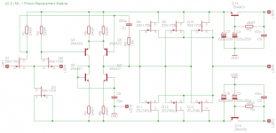
Eventually I finished the line modules. Many thanks to Erno Borbely who was very helpful
and sent me matched quads of 2SJ74V and 2SK170Vs. He also has the other parts in stock
and much more. Very recommended.
Attached is the final schematic I used. I´ve built a version with Fairchild
2SA1381 / 2SC3503 for test purposes too, seems to work equally well.
Hi,
For Toshiba JFET, is it OK to use matched SK/SJ BL grade at 7-8mA here ?
If I want to use 4402/4401 do I need to change resistor value ?
thanks
- Home
- Source & Line
- Analog Line Level
- Need to build JC 2 preamp