The radiation from a port is a solution of the Helmholtz equations. For simplicity's sake we regard the process as the movement of an incompressable "block" of air. That approach makes the computations a lot easier, but it is not nearer the physical reality. The incompressability itself is a result of the Helmholtz solutions. At high pressure levels, where non-linear effects due to the air flow occur, the models you mentioned are to be preferred. Application of the Boundary Element method is limited to the linear case.
To simulate the behaviour of a duct or port using BEM, you must choose the Edge Length parameter small enough, so that details of the port geometry can be represented in te calculation. An Edge Length of half the wavelength will be far too great
regards,
Tom
To simulate the behaviour of a duct or port using BEM, you must choose the Edge Length parameter small enough, so that details of the port geometry can be represented in te calculation. An Edge Length of half the wavelength will be far too great
regards,
Tom
The radiation from a port is a solution of the Helmholtz equations. For simplicity's sake we regard the process as the movement of an incompressable "block" of air. That approach makes the computations a lot easier, but it is not nearer the physical reality.
The reality is that the incompressible slug of air moving in and out of the port is changing the amount of air in the room outside the speaker. This forces the air around the speaker to compress and rareify creating sound. Precisely where does not matter much in practise in the far field at low frequencies because the wavelength will be long. How much though is precisely known and follows from the volume of air displaced.
So how much volume is displaced by the slug of air moving in and out of the port? In particular is it the same as that of the driver? If not then a conventional acoustic BEM code involving only boundary pressures and particle velocities without any sources within the volume will not "see" it and will predict an incorrect volume velocity within the port.
For those familiar with reading equations then the point may be clearer. The Lighthill acoustic analogy expresses a "full" acoustic wave equation with the terms handled by the BEM code on the LHS and the terms it neglects on the RHS. The neglected terms are the sources and sinks of sound within the volume. The only way to evaluate the neglected terms precisely is to discretise space and solve the mass, momentum and (optionally) energy equations (i.e. a CFD simulation). The usefulness of the acoustic analogies lies in spotting when one can avoid the details in the source terms and replace them with a known integral over space. The port volume velocity would be an example of this if it were acceptably approximated from, say, the typical 0D empirical approximations used in speaker design programs.
hello all
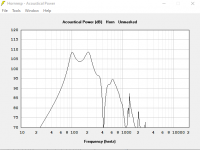
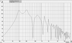
i will present 3 simulations, hornresp akabak 2.0 akabak 3.0 in attachement
so hornesp and akabak2.0 is similare so different of akabak 3.0
in akabak 3.0 driving value 1 isrms not select and source at 2.83 for input voltage in source and driver are in 2.83v rms
how to adjust akabak 3.0 correctly without having truncated curves
I only use the LEM part for simple script meshes for the different horns idicat in attachement
Attachments
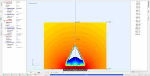
This seems very complicated design. You cannot share boundaries between subdomains, this is not correct. Every boundary or part of boundary what is in one subdomain, must be independent plane in CAD drawing.Do we have here any Akabak3 guru? Trying to model modified version of Void X-Air but I'm getting no errors and weird results. I've already simmed the cab in a LEM getting some plausible results but BEM+LEM is not my friend yet.
Would be anybody so kind and review my Akabak project? I'm particularly interested in checking the BEM boundaries definition as I had some difficulties with mesh generation in gmesh and mesh is not exactly what I would like it to be - in a nutshell - some BEM boundaries are shared between multiple subdomains.
Project overview
Cab construction: dual reentrant hornloaded 6th order bandpass ?
Simulation type: BEM+LEM
Processor: Intel(R) Core(TM) i5-10210U CPU @ 1.60GHz, 2112 Mhz, 4 Core(s), 8 Logical Processor(s)
BE-meshing + BE-solving time: 37m
Subdomains: 11
Interfaces: 15
Frequencies: 30Hz - 300Hz
Are 15 interfaces really needed? Are normals of interface elements in right directions? Are speaker element T/S parameters correct?
The reality is that the incompressible slug of air moving in and out of the port is changing the amount of air in the room outside the speaker. This forces the air around the speaker to compress and rareify creating sound. Precisely where does not matter much in practise in the far field at low frequencies because the wavelength will be long. How much though is precisely known and follows from the volume of air displaced.
So how much volume is displaced by the slug of air moving in and out of the port? In particular is it the same as that of the driver? If not then a conventional acoustic BEM code involving only boundary pressures and particle velocities without any sources within the volume will not "see" it and will predict an incorrect volume velocity within the port.
I don't think the aeroacoustic approach is indicated in the case of bass reflex enclosures. The air in the duct does not really move as a " lump" of air, just as the air in front of a cone does not move as a layer of air. The solution of the Helmholtz equations suggests a behaviour in the duct or close to the cone with an increased accesion to inertia, but that does not mean that the air is actually moving as a "lump" of air.
In akabak you would model the box using 3 subdomains: one for the interior, one for the volume of the duct, and one for the outside world. The latter subdomain is still a closed volume, because Neumann boundary conditions are assumed. The 3 subdomains are coupled using interface elements. There are no holes or sinks anywhere.
In practice, it is perfectly possible to calculate the radiation from a duct and determine the tuning of the box using the boundary element method. An additional advantage is that the baffle effect, that determines the "end correction" of the duct, is automatically taken care of.
best regards,
Tom
I don't think the aeroacoustic approach is indicated in the case of bass reflex enclosures. The air in the duct does not really move as a " lump" of air, just as the air in front of a cone does not move as a layer of air. The solution of the Helmholtz equations suggests a behaviour in the duct or close to the cone with an increased accesion to inertia, but that does not mean that the air is actually moving as a "lump" of air.
It looks like my explanation based on words and equations hasn't got across about the kind of physics missing. It is an interesting problem though because it isn't immediately apparent what will be missing from a typical BEM acoustical simulation. The results from a set of acoustic simulations with appropriate and inappropriate assumptions would make the point more clearly and I have added this to my to-do list. The software is still being developed so it won't happen soon but it is certainly an interesting example and so it is fairly likely to happen.
Hi I am new to this program and keep getting the message" Radation Polar data set empty" after I run a simulation . I did get some results a couple of days ago but now get this message every time . I think I have mistakenly changed something but can't find out what. Any ideas ? Many thanks
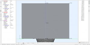
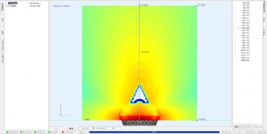
Waveguide Simulation
Hi Guys.
I'm trying to simulate a waveguide geometry but when I run the simulation something goes wrong with my results, there seems to be something in front of it hindering the wave propagation.
I'm using the normal interface that needs to be, I tried to turn off some elements but nothing worked, does anyone realize if my BEM setup is correct?
Thank you all.
Attachments
Are the only "tutorials" on how to use akabak 3 the couple videos on the site and youtube?
Those combined with the examples in the program, is that all a beginner who can't make sense of anything has to work off?
Would learning an older version, which I understand works completely differently, help me understand it any better?
Those combined with the examples in the program, is that all a beginner who can't make sense of anything has to work off?
Would learning an older version, which I understand works completely differently, help me understand it any better?
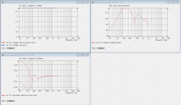
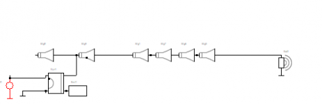
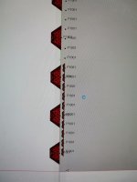
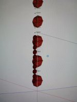
I've been trying to simulate a line array, but when i have more than 10-12 drivers, I get this error:
"Singularity in linear algebraic equation solver.
LUDecomp2 (6.27210971...)
Solving aborted"
The BE mesh and the BE solver show in green, the LE and the rest are the ones showing in red.
If I just delete drivers, it simulates properly, so I guess the method is not completely wrong... But I also don't know where to look.
I also tried to reduce the diameter of the diaphragm in case there was a clashing between the edge/tangent of the diaphragms, but I get the same error.
I guess is something basic that I am missing but I just can't see it, any ideas/comments are welcome
Attachments
 It's all good. I've attached them to your post and that is generally a good thing.
In Akabak 1, there was a limitation on how many elements you could have. It was about 52 or 55 as I recall. In simulating a 25 driver line array I remember I had to be very judicious with how many separate rear chambers etc in order to stay below the limit. This was a lumped element model, and maybe Akabak 3 is still relying on the Akabak 1 core?
I also deleted the LEM elements and only used the BEM diaphragms, and still no luck, I still get the "very high level; change range or move away the observation mesh from the source" or the singularity issue, depending on the number of diaphragms used.
Right now I have what I believe the most simplistic model which is: one node for each speaker position, exterior subdomain, with diaphragms nested in the subdomain, without any baffle and I still get this error, adjusting the range doesn't solve it, neither if I offset the 2D shell for mapping.
Could it be something really basic in the BEM global settings?
- Home
- Design & Build
- Software Tools
- AKABAK 3