If i could convert it to NGspice, i would probably switch
Attached your circlotron circuit simulation working using ngspice.
I have converted and cleaned up your ltspice ".net" output file. In principle it should run with current "ngspice pre-master" which includes the fix to allow "{}" calculations in ".model" parameters.
At simulation start you get this error:
Cannot compute substitute
Copies=56 Evals=114 Placeholders=4 Symbols=3 Errors=6
Numparam expansion errors: Run Spice anyway? y/n ?
Just ignore it with "y" to continue because the errors are due to unallowed model parameters like "mfg" which are of no relevance here.Copies=56 Evals=114 Placeholders=4 Symbols=3 Errors=6
Numparam expansion errors: Run Spice anyway? y/n ?
BR, Toni
Attachments
In fact it is possible to use temperature, voltages and currents in model parameter expressions. There was a bug in the parser for the VDMOS model. I have pushed a fix to branch pre-master.
...
Concerning the self heating models, we still have some discussions about the final implementation.
...
Thx Holger for the very fast fix! Works now with Ian's ltspice models.
See above example of the "circlotron".
About the vbic and vdmos self heating: is there a plan when it will be production ready and merged into pre-master/master?
BR, Toni
I have gSpiceUI installed but I was discouraged from using it the few times I tried it. My impression was immediately a very steep learning curve ahead. I reasoned if I wanted others to read my circuits and help me in case of difficulties, it was far more practical for me to use LTSpice instead.
Trying it another time I got the impression I was using KiCad. LTSpice is far simpler to use and used by many more people.
Trying it another time I got the impression I was using KiCad. LTSpice is far simpler to use and used by many more people.
Last edited:
Your opinion here is a bit off topic: we are not discussing which schematic gui is intuitive/better - we are discussing ngspice - the simulator core itself. Feel free to start your own thread/poll discussing gui features of open source schematic editors vs commercial (and currently "freeware") ltspice schematic editor....
LTSpice is far simpler to use and used by many more people.
BR, Toni
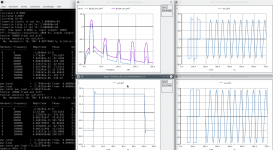
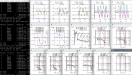
... maybe the learning curve is high, but the results of one sim run makes really fun and speeds up the development exponentially (as one of many benefits it helps to avoid a carpal tunnel syndrome). Attached a screenshot of a high power class G amplifier in development using 8 pairs TTC5200/TTA1943 and 8 pairs IRFP240/9240.
Includes SOA of VAS, drivers, output drivers of all 5 power steps
tian probe results of feedback loop and vas feedback loop
fft, harmonic distortions, output power etc ...
Thanks to David Zan supporting me with outstanding good ideas for going green!
Have fun, Toni
Includes SOA of VAS, drivers, output drivers of all 5 power steps
tian probe results of feedback loop and vas feedback loop
fft, harmonic distortions, output power etc ...
Thanks to David Zan supporting me with outstanding good ideas for going green!
Have fun, Toni
Attachments
All right, granted. If the simulator engine (core) is that powerful it is worthy of a good look. I tried to install the core but ngspice is not available in the distribution's repositories although gspiceui has references to it.astx said:Your opinion here is a bit off topic: we are not discussing which schematic gui is intuitive/better - we are discussing ngspice - the simulator core itself.
Code:
$ apt-get install -s ngspice
NOTE: This is only a simulation!
      apt-get needs root privileges for real execution.
      Keep also in mind that locking is deactivated,
      so don't depend on the relevance to the real current situation!
Reading package lists... Done
Building dependency tree
Reading state information... Done
Package ngspice is not available, but is referred to by another package.
This may mean that the package is missing, has been obsoleted, or
is only available from another source

E: Package 'ngspice' has no installation candidate
Attached your circlotron circuit simulation working using ngspice.
I have converted and cleaned up your ltspice ".net" output file. In principle it should run with current "ngspice pre-master" which includes the fix to allow "{}" calculations in ".model" parameters.
At simulation start you get this error:Cannot compute substituteJust ignore it with "y" to continue because the errors are due to unallowed model parameters like "mfg" which are of no relevance here.
Copies=56 Evals=114 Placeholders=4 Symbols=3 Errors=6
Numparam expansion errors: Run Spice anyway? y/n ?
BR, Toni
Thank you so much !
In fact it is possible to use temperature, voltages and currents in model parameter expressions. There was a bug in the parser for the VDMOS model. I have pushed a fix to branch pre-master.
You will need to enable PS compatibility.
The following test seems to be o.k.:
Concerning the self heating models, we still have some discussions about the final implementation.Code:VDMOS output m1 d g s IRF610 *.model IRFZ48Z VDMOS (Rg = 1.77 Vto=4 Rd=1.85m Rs=0.0m Rb=3.75m Kp=25 Cgdmax=2.1n Cgdmin=0.05n Cgs=1.8n Cjo=0.55n Is=2.5p tt=20n mfg=International_Rectifier Vds=55 Ron=8.6m Qg=43n) .model IRF610 VDMOS ( Rg=5 Vto={4.30-6m* ( 0+temp-25 ) } Lambda=3m Rs={35m* ( 1+3.5m* ( 0+temp-25 ) ) } vd d 0 1 vg g 0 1 vs s 0 0 Bvt0 1 0 v = 4.30-6m* ( 0+temp-25 ) Bt1 2 0 v=temper Bt3 3 0 v=temp .dc vd -1 15 0.05 vg 3 10 1 .control set temp=25 run print v(1)[0] v(2)[0] v(3)[0] showmod plot vs#branch ylimit -5 15 set temp=80 run showmod plot vs#branch ylimit -5 15 .endc .end
Holger
Even though this example will work (at the moment with actual pre-master and PS compatibility not!) I see large problems to implement an alternative temperature model in parallel for devices with an own built-in temperature model like vdmos. Which model has priority? The built-in or the parameter based? What is happen in dc temp sweeps?
May be it make sense for simple passive devices where I switch of the built-in temp model or for controlled sources w/o temp modelling.
Dietmar
ngspice-32
ngspice-32 is available for circuit simulation. You may download it from ngspice - Browse /ng-spice-rework/32 at SourceForge.net for various operating systems.
Three major enhancements are included in this release.
ngspice plotting has been enhanced considerably. Now you may choose colors for background, or grid, graphs and labels, and you may select individual line thickness for grid/labels or graphs, as well as various fonts for labeling. Also the postscript-to-file or gnuplot export have benefitted.
ngspice now reads unicode characters for file and directories names and for graph labels. Several examples in directory ngspice/examples/utf-8 demonstrate the capabilities.
The VDMOS power MOS model has been upgraded. It now contains 54 model parameters to cover dc, ac, and thermal aspects. The model supports weak inversion, quasi saturation, and forming of the triode region, breakdown, body diode etc. All major parameters have their corresponding linear and quadratic thermal coefficients. A completely new feature is the modeling of self-heating. All power losses in the transistor result in heat, which leads to a temperature rise. The resulting temperature influences again the electrical behavior in a feedback loop. Electro-thermal modeling is used, combining electric and thermal circuits. To get rid of the heat, you may apply and simulate heat sinks, both statically and dynamically. Some example simulations are supplied in ngspice/examples/vdmos. For more information I have attached an excerpt from the ngspice manual, describing our VDMOS implementation. And ngspice is open source, so you may have a look at the VDMOS model source code as well. Dietmar Warning has done a really nice job to get this up and running.
ngspice has a command line interface, but it may be used in conjunction with KiCAD (KiCad EDA) or some other GUI (see
Ngspice, the open source Spice circuit simulator - Schematic entry and GUIs, Simulation Environments).
Holger
(ngspice maintainer)
Attachments
Last edited:
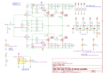
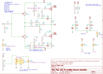
PassLabs F5 Turbo V2 simulation with self-heating
The KiCAD/Eeschema/ngspice example of the PassLabs F5 Turbo version 2 is set up to run with recent ngspice-32.
The power transistors symbols and their VDMOS model now have five terminals: The electrical nodes drain, gate, source, and two thermal nodes junction temperature and case temperature. We simulate the electric circuit as usual, but have a thermal circuit in parallel. Three model parameters are dedicated to self-heating: RTHJC, the junction to case thermal resistance (from the data sheet), CTHJ, the thermal capacitance of the packaged chip, (to be estimated, e.g. by taking the thermal capacity of 1g of Cu), and RTHCA, the thermal resistance if no heat sink is provided (typically around 100 K/W). The choice of the power transistors IRFP9240 and IRFP240 is probably not the optimum selection, it is simply due to transistor parameter availability.
The transient simulation settings in this example are made for thermal evaluation (which requires a simulation time of few seconds, until thermal stability is achieved). For a detailed circuit analysis one probably would use the final device temperatures as estimated and then choose a smaller step size resolution, e.g.
.tran 10u 100m
The CPU time for 5s of simulated time is approx. 1 to 2s.
The thermistors TH1 and TH2 have got their own device model (a subcircuit) and now have three terminals: two electric nodes and one thermal node. The thermal node is coupled to the thermal node of the heat sink.
The heat sink comprises of a thermal resistor between device and sink (glueing of the package to the heat sink surface), the heat sink thermal resistance and its thermal capacitance.
Still missing is a self heating model of the power diodes to simulate their heat sink requirements.
In addition to the KiCAD/Eeschema files there is also a ngspice netlist available for direct use in standard ngspice.
The previous Eeschma files (without self-heating, only transistor selfheating withot thermistors, are available as well.
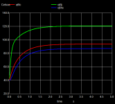
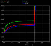
The picture shows the temperature rise of transistor Q6.
The KiCAD/Eeschema/ngspice example of the PassLabs F5 Turbo version 2 is set up to run with recent ngspice-32.
The power transistors symbols and their VDMOS model now have five terminals: The electrical nodes drain, gate, source, and two thermal nodes junction temperature and case temperature. We simulate the electric circuit as usual, but have a thermal circuit in parallel. Three model parameters are dedicated to self-heating: RTHJC, the junction to case thermal resistance (from the data sheet), CTHJ, the thermal capacitance of the packaged chip, (to be estimated, e.g. by taking the thermal capacity of 1g of Cu), and RTHCA, the thermal resistance if no heat sink is provided (typically around 100 K/W). The choice of the power transistors IRFP9240 and IRFP240 is probably not the optimum selection, it is simply due to transistor parameter availability.
The transient simulation settings in this example are made for thermal evaluation (which requires a simulation time of few seconds, until thermal stability is achieved). For a detailed circuit analysis one probably would use the final device temperatures as estimated and then choose a smaller step size resolution, e.g.
.tran 10u 100m
The CPU time for 5s of simulated time is approx. 1 to 2s.
The thermistors TH1 and TH2 have got their own device model (a subcircuit) and now have three terminals: two electric nodes and one thermal node. The thermal node is coupled to the thermal node of the heat sink.
The heat sink comprises of a thermal resistor between device and sink (glueing of the package to the heat sink surface), the heat sink thermal resistance and its thermal capacitance.
Still missing is a self heating model of the power diodes to simulate their heat sink requirements.
In addition to the KiCAD/Eeschema files there is also a ngspice netlist available for direct use in standard ngspice.
The previous Eeschma files (without self-heating, only transistor selfheating withot thermistors, are available as well.
The picture shows the temperature rise of transistor Q6.
Attachments
PassLabs F5 Turbo V2 simulation with short circuit
This is an enhacement of the previously shown KiCAD/Eeschema example of the PassLabs F5 Turbo version 2.
The transient simulation runs up to 6 s. At time=4 a short circuit is generated at the output by switching a relay with low (19m Ohms) resistance parallel to the output, leading to an immediate (<100ms) thermal runaway and destruction of the output transistors.
The 10 mOhm resistor may be replaced by a 8 Ohm resitor just to show what happens when the load switches from 8 to 4 Ohms. If you have KiCAD/Eeschema running, you may change the RON value by clicking onto the RON=10m text near the relay and change 10m to 8.
The three trim pots P1 to P3 may be changed similarily, to allow balancing of the amplifier by changing the 'ratio' which detemines the pot's wiper position.
The power supply is ramping up after a short delay to allow ngspice to settle at the surrounding temperature (here set to 40 °C).
The input voltage is set by the second entry in sin(0 2 1k 5m), frequency by the third entry. A short delay of 5m before ac in starts (fourth entry) may be used to look at the quit output, useful for trimmimg the output dc offset.
The Eeschema text box '*simulation data' determines the transient simulation step size and duration. In addition another script is included (loaded) from a file to allow simulation and plotting with external ngspic from the Eeschema Tools->Generate Netlist->RunSimulator command sequence. Several plots are generated, like output and input voltages, thermistor resistance, output current, and power supply currents.
In addition to the KiCAD/Eeschema files there is also a ngspice netlist available for direct use in standard ngspice.
Attachments
Last edited:
Another update to the F5 V2 simulation
Attached there is a new, updated zip file with an KiCAD/Eeschema/ngspice project to simulate the Pass Labs F5 Turbo V2 amplifier.
New features are: improved hint to install the project in readme.txt, update to the standard ngspice script with adding some fft, simulating 8 Ohms and 4 Ohms load in a single run, parameterizing haet sink data, etc.
Have fun!
Attachments
Pass Labs F6 KiCAD/ngspice simulation
Two versions of the F6 amplifier are simulated:
F6thermal-enh.sch is close to the design found at F6 Illustrated Build Guide. Two Enhancement NMOS power transistors IRFP240 are used. Two types of feedback are employed, via the source resistors R13 and R14 and via the voltage divider R1/R2. Networks with trimpots P1 and P2 set the bias for each transistor.
F6thermal-minimal.sch is a minimal version of this class A amplifier: 8 resistors, 2 JFETs, 2 Depletion mode NMOS power transistors (IXYS IXTH16N10), and the transformer. No capacitors (of course except for ther power supply that is not modelled here), no bias networks. The ngspice thermal VDMOS model parameters are only coarsely estimated from the data sheet, there is currently no model available from IXYS. A device mismatch is assumed, threshold voltages are set to -3.7 and -3.2 V. The symmtetry of the amp is achieved by setting resistor R13 appropriately, until the mean output voltage (aka the dc offset) is close to 0. Of course we do not have a 10 A trimpot, but one may use several resistors in parallel, and add them step by step until the correct value is found. Again feedback is by the source resistors R13 and R14 and via the voltage divider R1/R2.
More information on setting up the simulation is found in file readmeF6.txt from the attached zip file.
To state it clearly: these are simulations. I did not build anything. The models are coarse. So the minimal amp may work, but it also may happen that the transistors burn away immediately. It is an idea shown here, that may need further investigations.
Attachments
Last edited:
- Home
- Design & Build
- Software Tools
- Installing and using ngspice - an opensource simulator