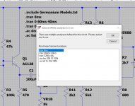
One thing you can do is set them all up as directives as shown here and when you click run you get offered what particular directive you want to run.
You pick one and click OK. All good, it runs. All the other directive get prefixed by ; instead of .
Then hit F9 (undo) and all the directives are changed back to . again.
So any of those five directive can be run with one single press of 'F9' followed by run.
I'm sure Mike didn't envisage that though.
Attachments

And I'm back to LTspice IV and sent Analog Devices support a rather strongly worded support request, you don't break functionality that people have used and enjoyed for well over a decade of LTspice use, that's ridiculous and stupid, or rather ridiculously stupid.
I agree, it's a los for mankind and electronics people alike.
Maybe someone will repair this functionality.
Then it will be a real happy xmass.
Amen! 😀
Almost all LTspiceXVII models are suitable for LTspiceIV. The incompatibility arose because a new time function was added.
I keep a backup in cloud storage. This is Yandex Disk.
LTspiceXVII_2019Jan29.zip — Yandex.Disk
I keep a backup in cloud storage. This is Yandex Disk.
LTspiceXVII_2019Jan29.zip — Yandex.Disk
Almost all LTspiceXVII models are suitable for LTspiceIV. The incompatibility arose because a new time function was added.
I keep a backup in cloud storage. This is Yandex Disk.
LTspiceXVII_2019Jan29.zip — Yandex.Disk
Thanks! Downloaded and put in a safe place.
Hi All
Merry christmas.
I have a question about a schematic from ltspice who is used for design a resonant supply. I have multi voltage system for tube sound.
I did try this to simulate but it I need to regulation below resonat poin en need to limit the shift such that it regulates.
Looks like this do work not good, I do not now how to set Fmax and Fmin to get these different modes.
As we now resonant supply's can work above and below resonance, and Maybe somebody now how to set that up in this schematic. below resonant is best it does now get above and regulation does not work, I use program for setup transformer.
Maybe there are more models for this kind of simulation,er is I remember also a spcial simulator for that.
regards
Attachments
I am running the attached circuit and get the following error
Unknown subcircuit called in xu2 n030 pot_lin rot=500 wiper=500
I have tried to chase down the missing files from the .asc in order to run the sim. Any help is appreciated.
Unknown subcircuit called in xu2 n030 pot_lin rot=500 wiper=500
I have tried to chase down the missing files from the .asc in order to run the sim. Any help is appreciated.
I am running the attached circuit and get the following error
Unknown subcircuit called in xu2 n030 pot_lin rot=500 wiper=500
I have tried to chase down the missing files from the .asc in order to run the sim. Any help is appreciated.
Potmeters have a fault, maybe names wrong or so.
Im have done pot from pot and switch included now in your zip file.
I have them already put them in your schematic but you need to install pot&switch.zip first.
Attachments
I am running the attached circuit and get the following error
Unknown subcircuit called in xu2 n030 pot_lin rot=500 wiper=500
I have tried to chase down the missing files from the .asc in order to run the sim. Any help is appreciated.
You have simply forgotten to place the statement
.include potentiometer_standard.lib
on your schematic.
Incidentally, your post suggests that you set wiper=500, but it should have a value between 0 and 1. However, on the schematic it is showing as 0.5, which is OK.
And I'm back to LTspice IV and sent Analog Devices support a rather strongly worded support request, you don't break functionality that people have used and enjoyed for well over a decade of LTspice use, that's ridiculous and stupid, or rather ridiculously stupid.
Hmm...
Linear Technology paid Mike Englehardt and his team to develop and maintain LTspice, but despite that they gave it freely to the EE community. We are not even asked to hand over our email addresses and register. It's an industrial strength programme that would have cost thousands some years ago.
I think it's a great application, and moreover we can use it without even getting out our credit cards. If it has a few quirks in its UI, I'm more than happy to live with them.
Linear Technology is now part of Analog Devices, and it's great that Analog are continuing to maintain and develop LTspice. The on-board library has been greatly expanded with Analog's devices and the programme has been developed in a number of ways. Most importantly, it is still freely available to us all.
The issue about the way multiple simulation commands are handled is something that has been looked at many times both in this forum (as noted by Mooly) and on the LTspice users' group. It was changed by design when XVII replaced IV. In the context of the capabilities of LTspice available to us all, it is a very minor inconvenience. And it's not going to get changed back to the old way.
Despite all this, you sent support a "rather strongly worded support request"? You think the change is "ridiculous and stupid, or rather ridiculously stupid". Are you trying to p*** off support big time? Have you given any consideration to what might happen if Analog gets annoyed by (non-paying) LTspice customers? Can you imagine a world without LTspice freely available?
If you are really so annoyed by the UI of XVII, then please either use IV (last updated 4.5 years ago, and it will not get any more updates), switch over to one of the open source alternatives, or get your wallet out. There are plenty of alternatives on the market if you don't like LTspice.
mje243/mje253 spice models - completely different results
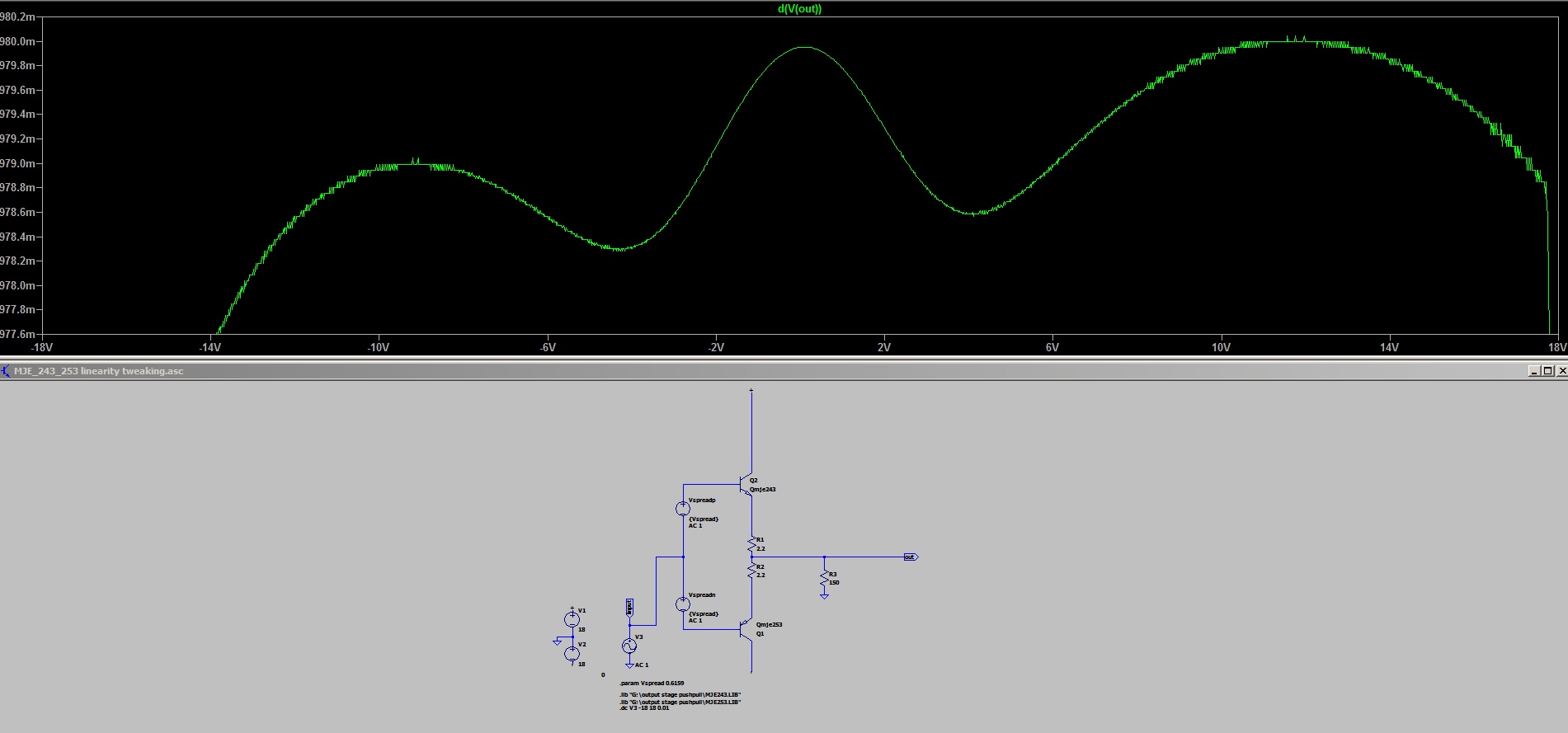
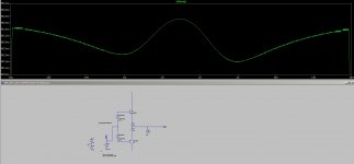
I tried to run wingspread simulations to compare the gain curve of two different spice models. While I expected to see differences in the gain distribution the almost opposite direction of the slope and the depth of the waviness of the curve surprised me a bit.
On-semi spice models
Cordell spice models
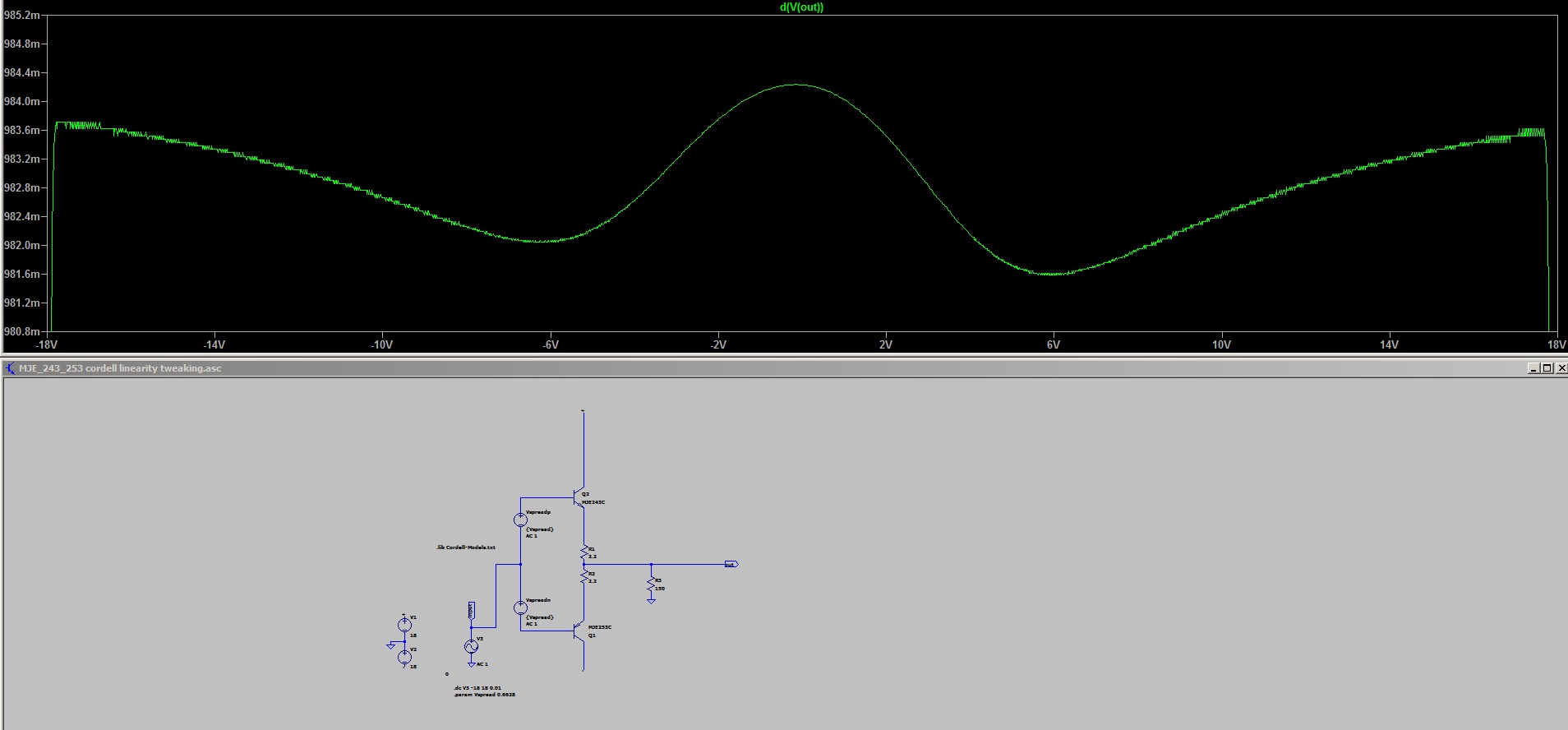
I believe that Bob Cordell's models can be trusted, although the smaller and more rippled gain on the npn side is somewhat counterintuitive. On the other hand, I have read about the problems the factory on_semi models cause with ac analysis and the difference in the dc transfer of the two transistors is glaring here. And this is where doubts arise about the accuracy of other available models. I've just started exploring the simulation world from so-called 'kitchen side' and I can't quite verify how the code matches up to reality. Can the stock LTspice library be trusted and which manufacturer's resources should be avoided?
I tried to run wingspread simulations to compare the gain curve of two different spice models. While I expected to see differences in the gain distribution the almost opposite direction of the slope and the depth of the waviness of the curve surprised me a bit.
On-semi spice models
Cordell spice models
I believe that Bob Cordell's models can be trusted, although the smaller and more rippled gain on the npn side is somewhat counterintuitive. On the other hand, I have read about the problems the factory on_semi models cause with ac analysis and the difference in the dc transfer of the two transistors is glaring here. And this is where doubts arise about the accuracy of other available models. I've just started exploring the simulation world from so-called 'kitchen side' and I can't quite verify how the code matches up to reality. Can the stock LTspice library be trusted and which manufacturer's resources should be avoided?
Attachments

I tried to run wingspread simulations to compare the gain curve of two different spice models...
I had tried once to make a database of transistor models, but found that many of them gave very different results from the datasheet, and abandoned the project.
The most accurate models were undoubtedly Bob Cordell's. I wouldn't really trust the models that one finds floating around the internet, there's a huge amount of out of date and inaccurate stuff out there. The stock library models are probably OK, though I stick to Bob's as much as possible.
The jagged effect in your plots are rounding errors due to the limited resolution of LTspice's maths routines. To improve the resolution, the first steps to take are to include the following statements on your circuit:
.option plotwinsize=0
.option numdgt=7
The first disables data compression, the second sets double precision for the output data.
For consistency, I personally think it's a good idea to use .plt files to force all wingspread plots to have the same y-axis limits, e.g. 0.9 to 1.0 - this makes it much easier to make valid visual comparisons between plots.
It's virtually impossible to see the details of your sims from your screenshots. If you post a zipped folder containing your .asc files, along with all supporting files such as models and .plt files, I'm sure either I or someone else will be able to offer additional advice.
Thanks for your reply, your comment has helped me to clear up a few doubts. I read some really negative opinions about some of the models released by onsemi over a decade ago. It seems they haven't updated anything since then - the same files are still hanging on their site. It is a little surprising. After all, these aren't some files flying around the internet but official models of their own products, right? At least I know I can't find anything more accurate than Cordell's bjts. 🙂The most accurate models were undoubtedly Bob Cordell's. I wouldn't really trust the models that one finds floating around the internet, there's a huge amount of out of date and inaccurate stuff out there. The stock library models are probably OK, though I stick to Bob's as much as possible.
Ok, but it really isn't anything fascinating. A simple push-pull stage with idealised bias sources with the voltage selected to simply achieve a reasonable compromise in the linearity of that stage at the lowest expected load resistance. Ic is slightly different but the characteristic shapes are more or less preserved for the current range that interests me. With the onsemi models, the pnp side is clearly weaker and shows a stronger drop in gain (static crossover distortion) while the Cordell's models show the opposite tendency (npn weaker). Here the improved (according to your recommendations) clearer graph containing results of these two simulations:It's virtually impossible to see the details of your sims from your screenshots. If you post a zipped folder containing your .asc files, along with all supporting files such as models and .plt files, I'm sure either I or someone else will be able to offer additional advice.

If you think about it, choosing a side driven through the bias spreader with non-zero impedance can increase or decrease distortion. It may turn out that closer to the ideal cfp vbe multiplier will give a worse result than a simple circuit based on one transistor or a series of diodes.
 😀
😀It's not a big deal but would be interested to know what trend these components actually exhibit and why it happens. I would guess that the hfe itself has rather little to say here, so is it related to the base resistance or perhaps one of the parameters responsible for beta droop?
Attachments
Last edited:
Guys can I put a question in between: does anyone have a spice model for the LM195/LM395 ultra reliable power transistor?
I know it is very similar to the LM117/LM137 of which I have a model, but I can't seem to modify it to work as an LM195/LM395.
Jan
I know it is very similar to the LM117/LM137 of which I have a model, but I can't seem to modify it to work as an LM195/LM395.
Jan
Hi Jan,
It doesn't surprise me that you can't find a SPICE model of the LM395. I doubt that all of the features that make it "ultra reliable" - some of which aren't disclosed in the data sheet - would be reflected in a commercially released SPICE model. So even if you had one its' usefulness would be limited.
At LTC we looked at making a version of the LM395 but the sales were so low it didn't make sense. To be honest I'm surprised TI hasn't EOL'd it.
Yeah, I can imagine that. Last time I used them was for the heater is a thermal control system. ;-)
I am interested in something that mimics the frequency dependent behavior, not so much all the protection and limiting stuff.
I wonder if I should just draw out the LM317 model schematic ...
Jan
I am interested in something that mimics the frequency dependent behavior, not so much all the protection and limiting stuff.
I wonder if I should just draw out the LM317 model schematic ...
Jan
Hi Jan,
A "home made" model probably wouldn't be worth the time & effort. Those schematics - at least the ones we did at LTC - were what we called "representational". Reality was quite different. Even if you had the right schematic you wouldn't have the right transistors.
Bottom line" I would say this is a bench job.
- Home
- Design & Build
- Software Tools
- Installing and using LTspice IV (now including LTXVII), From beginner to advanced