Yes but the LM317 would be representable enough, right? It would just be a matter of removing the reference; I know that the two devices are identical except that for the LM395, some of the mask metallization is omitted.
Or am I looking at it too simplistic?
Jan
Or am I looking at it too simplistic?
Jan
Jan,
Let's put it this way: if I wanted to characterize the AC performance of the LM395, I would do it on the bench. I'm not saying you definitely can't make a decent model of the LM395, but it is going to be a lot of work... and how will you verify the model's performance? On the bench of course.
Bottom line, unless you really need a model for some reason, I think the fastest path to enlightenment will be on your bench.
YMMV.
No I mean measure the performance in the circuit I'm designing and then determining whether that is acceptable for my requirements. But hey that's just me, I'm a bench kind of guy. If you seek enlightenment on another path more power to you!
Of course! I can do that.
When I was studying at Raytheon they had a simulator that had A/D and D/A interfaces to use hardware-in-the-loop. This is just like it, minus the simulator ;-) .
What was I thinking ...
Jan
When I was studying at Raytheon they had a simulator that had A/D and D/A interfaces to use hardware-in-the-loop. This is just like it, minus the simulator ;-) .
What was I thinking ...
Jan
I can't say that's wrong, but I can't say it's right either.
My suspicion is that it's not set to a nominal value like 100 uA but rather it's scaled to the transistor whose base it drives so they track each other over temp & process variations but there's no way to tell. Again, representational...
You should have asked a few years ago, I could have just asked Dobkin, I bet he remembers! I don't do linkedin but if you do & you can find him he might answer you.
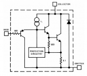
I get "I1 = 26 microamperes". Here is my arithmetic
I1 = (VBE / 500) / (Beta / 3)
I1 = (0.65 / 500) / (150 / 3)
I1 = 1.3E-3 / 50 = 2.6E-5 = 26 uA
I1 = (VBE / 500) / (Beta / 3)
I1 = (0.65 / 500) / (150 / 3)
I1 = 1.3E-3 / 50 = 2.6E-5 = 26 uA
Because I want I1 to be "comfortably" greater than the base current of the NPN. I decided that I'm comfortable when I1 = 3 * Ibase. Individual preference. Other designers may prefer a larger safety margin, to handle fast transients and to charge/discharge the inevitable capacitances on that node, quickly.
_
_
Last edited:
This is what I have.
* WARNING : please consider following remarks before usage
*
* 1) All models are a tradeoff between accuracy and complexity (ie. simulation
* time).
* 2) Macromodels are not a substitute to breadboarding, they rather confirm the
* validity of a design approach and help to select surrounding component values.
*
* 3) A macromodel emulates the NOMINAL performance of a TYPICAL device within
* SPECIFIED OPERATING CONDITIONS (ie. temperature, supply voltage, etc.).
* Thus the macromodel is often not as exhaustive as the datasheet, its goal
* is to illustrate the main parameters of the product.
*
* 4) Data issued from macromodels used outside of its specified conditions
* (Vcc, Temperature, etc) or even worse: outside of the device operating
* conditions (Vcc, Vicm, etc) are not reliable in any way.
** Standard Linear Ics Macromodels, 1993.
** CONNECTIONS :
* 1 INVERTING INPUT
* 2 NON-INVERTING INPUT
* 3 OUTPUT
* 4 POSITIVE POWER SUPPLY
* 5 NEGATIVE POWER SUPPLY
.SUBCKT LM193 1 3 2 4 5 (analog)
**********************************************************
.MODEL MDTH D IS=1E-11 KF=1.050321E-32 CJO=10F
* INPUT STAGE
CIP 2 5 1.000000E-12
CIN 1 5 1.000000E-12
EIP 102 0 2 0 1
VIO 10 102 438.3U
EIN 16 0 1 0 1
RIP 10 11 6.500000E+01
RIN 15 16 6.500000E+01
RIS 11 15 1.939046E+02
DIP 11 12 MDTH 400E-12
DIN 15 14 MDTH 400E-12
VOFP 12 13 DC 0.000000E+00
VOFN 13 14 DC 0
IPOL 13 0 100E-06
CPS 11 15 5.5E-09
DINN 17 13 MDTH 400E-12
VIN 17 5 0.000000e+00
DINR 15 18 MDTH 400E-12
VIP 4 18 1.500000E+00
FCP 4 5 VOFP 0.175
FCN 5 4 VOFN 0.175
FIBP 2 0 VOFN 2.000000E-08
FIBN 0 1 VOFP 2.000000E-08
* AMPLIFYING STAGE
RG1 5 19 2.85E+05
RG2 4 19 2.85E+05
DOP 19 25 MDTH 400E-12
VOP 4 25 1.097
DON 24 19 MDTH 400E-12
VON 24 5 1.097
FIP 0 19 VOFP -104
FIN 0 19 VOFN -104
EOUT 26 5 19 5 1
.MODEL NMOD NPN(IS=0.1E-09 BF=4000)
RBOUT 27 26 800K
QOUT 103 27 28 28 NMOD
REOUT 28 5 20
RSOUT 3 0 1E+12
VNUL 3 103 0
DSTOP 32 103 MDTH 400E-12
HSTOP 32 33 VNUL 135
VSTOP 33 5 0.5
.ENDS
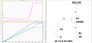
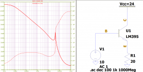
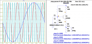
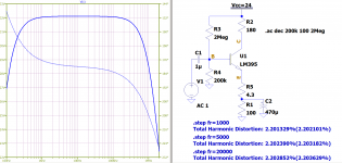
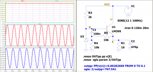
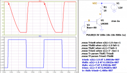
Model, symbol and tests:
Attachments
I took the model from TI (I have several of them). I threw out some transistors, resistors and capacitors. I changed one resistor to a 500 ohm rating and one end of that resistor became the base. If you look, you will see the lines commented out. I did not try to make the circuit 100% correct. I figured it would do just fine. Some of the auxiliary circuits are different than the LM317. They are designed to trigger (turn on) the reference voltage. But the circuit works this way too. And this circuit is outside of amplifier transistors.
I just wish I could do that, I mean I understand what you did, just wasn't able to find the parts.
Thanks for all your help Alexander!
Jan
Thanks for all your help Alexander!
Jan
The model I sent does not match the datasheet. When I found this out, I corrected the resistor values to those given in the schematic in the datasheet. But it turned out even worse. Maybe that is why the spice model was not uploaded. I decided to ignore these resistor values. I had to expand the list of parameters. I entered the breakdown voltages.
I am sending the new model and test circuits. I would be glad if someone would test the model and give comments.
I am sending the new model and test circuits. I would be glad if someone would test the model and give comments.
Attachments
- Home
- Design & Build
- Software Tools
- Installing and using LTspice IV (now including LTXVII), From beginner to advanced