Sorry Ask, there are still issues, it seems.
The fade-in is exponential, not raised-cosine, this gives a kinky spectrum and the default of 2 times the initial period time is problematic, too. With a start freq of 1Hz this means the stimulus is invalid during the first two seconds. Depending on the length used it may fade-in longer than the whole waveform runs. With shorter fade-in's the problem remains, there is a kink visible in the waveform itself with disastrous effects on the spectrum (and that would give artifacts in the distortion components, wouldn't it?)
Also the inverse still doesn't look right to me. I recognize that you construct the inverse in the freq domain so as to give a dirac by design: after reversing the inverse I get a reasonably (<> fully) perfect dirac when I convolve with the stimulus, no matter how corrupted it looks -- but only if I *don't* extend the stimulus on the ends with enough zeros, otherwise there are strong artifacts (echo pulse). This resulting "loopback" pulse should be artifact-free at any rate and should IMHO resemble the bandpass response used for the stimulus. That's at least what I did in my own experiment and I get a perfect artifact-free IR when loopback folding and the sprectra also are as clean as can be, so I doubt it's a computation artifact from Audition's convolver.
- Klaus
Attachments
Re: Re: Re: Re: Re: Re: Keep it simple!
Hi,
I didn't want to offend You, and yes I was dimissive right from the start. What would You tell me if I offer You - to bettern the sound - to stick Your fingers in Your ears? I doubt whether You would discuss that topic with me! John K. has had opened a thread on simulation integration some time ago. We could discuss that there. I have exercised dimissive argumentaton even before this thread ;-)
cheers
dlr said:
Your attitude has been from the beginning dismissive on that aspect, repeatedly as well. There may not be agreement on who is "arguing this thread to trash". Agreed that it's up to the "implementer". That is not you. I see no problem in discussing it. Start another thread if it bothers you.
Dave
Hi,
I didn't want to offend You, and yes I was dimissive right from the start. What would You tell me if I offer You - to bettern the sound - to stick Your fingers in Your ears? I doubt whether You would discuss that topic with me! John K. has had opened a thread on simulation integration some time ago. We could discuss that there. I have exercised dimissive argumentaton even before this thread ;-)
cheers
Logsweep
Thank you Klaus for your cooperation
The logsweep convolution is the core of HOLMImpulse, so we must agree on how this is working.
(To others: That is why Klaus and I are spending all this time not measuring speakers...)
Klaus and others I have got some questions...
1. Wave file bug?
You got error-messages when importing my wave-files. Do you still have these problems?
2. Fadein and fadeout amplitude
I use a 1/2 raised cosine to damp the amplitude of the signal.
The problem with the wavepacket is to get started.
Why do you want to use a full raised cosine?
3. Fadein and fadeout adjustments
My wavelengths approach is based on wavepacket ideas. If you want to make a 1Hz wavepacket, containing mostly 1 Hz frequencies, then you would need several seconds. I must of course improve it so I take into account that the frequency increases with a logsweep, but at 10Hz, I did not have this problem.
(You can set the fadin wavelengths to 0.1 if you prefer)
4. LogSweep and starting frequency
Let us say we measure at 44.1 kHz, from 1 Hz to 22 kHz, then 1/3 of the measurement time we are measuring frequencies below 20 Hz - We do not want that. BTW Farina starts at 20Hz - I find a good compromise starting at 10 Hz. See attachment for the 1Hz example
5. The inverse signal - Convolution is circular - zero extension
You must make a circular convolution of the inverse signal and the signal. Extending with zeroes? If you extend with zeroes before and after the signal and the inverse before making the circular convolution - yes then of course you will get garbage.
If extending the signal with zeroes before and after we must recalculate the inverse (HOLMImpulse does this when measuring)
I could add an option with adding zeroes to the saved signal and the inverse. Eg. if we have signal length 2^19 = 524288, then I will add 2^18 = 262144 zeroes before an after so that the new length of the zero extended signal and the NEW recalculated inverse is 2^20 = 2^19 + 2*2^18 = 1048576.
Is this what you want?
Attachments
Re: Logsweep
If you use a half cosine fade in the slope discontinuity at the end of the fade in will mean you deviate further than necessary from a truly log sweep which will affect the ability to properly separate the distortion harmonics. Using a fixed time period for the fade in (e.g. 100ms) works well.2. Fadein and fadeout amplitude
I use a 1/2 raised cosine to damp the amplitude of the signal.
The problem with the wavepacket is to get started.
Why do you want to use a full raised cosine?
3. Fadein and fadeout adjustments
My wavelengths approach is based on wavepacket ideas. If you want to make a 1Hz wavepacket, containing mostly 1 Hz frequencies, then you would need several seconds. I must of course improve it so I take into account that the frequency increases with a logsweep, but at 10Hz, I did not have this problem.
Re: Re: Re: Re: Re: Re: Re: Keep it simple!
Your arguments are incomplete and do not address relevant issues. The dismissive position is a disservice and does nothing to help "better the sound", quite the contrary.
Dave
wxa666 said:
Hi,
I didn't want to offend You, and yes I was dimissive right from the start. What would You tell me if I offer You - to bettern the sound - to stick Your fingers in Your ears? I doubt whether You would discuss that topic with me! John K. has had opened a thread on simulation integration some time ago. We could discuss that there. I have exercised dimissive argumentaton even before this thread ;-)
cheers
Your arguments are incomplete and do not address relevant issues. The dismissive position is a disservice and does nothing to help "better the sound", quite the contrary.
Dave
Re: Re: Logsweep
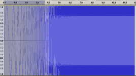
I measured six combinations: Loopback, 48kHz, ASIO, start at 10Hz varying signal lengths (2^18 and 2^20) and the fade-in's and -out's :
a) fade-in 0, fade-out 0
b) fade-in 1, fade-out 30
c) fade-in 10, fade-out 300
The effect on THD can clearly be seen, on both ends. Note that for N=18 the fade-in=1 gives the best result (but still not the known level for the card, which is below -90dB at any from 10Hz to 1kHz). This might come from two things :
1) the kink in the waveform (in case of fade-in=0 right at the start) givensmore than necessary harmonics,
2) to a presumably way lesser extent, the loss of S/N as the stimulus has low amplitude in the fade areas.
- Klaus
I think both my reasoning and my measurements back this.JohnPM said:If you use a half cosine fade in the slope discontinuity at the end of the fade in will mean you deviate further than necessary from a truly log sweep which will affect the ability to properly separate the distortion harmonics. Using a fixed time period for the fade in (e.g. 100ms) works well.
I measured six combinations: Loopback, 48kHz, ASIO, start at 10Hz varying signal lengths (2^18 and 2^20) and the fade-in's and -out's :
a) fade-in 0, fade-out 0
b) fade-in 1, fade-out 30
c) fade-in 10, fade-out 300
The effect on THD can clearly be seen, on both ends. Note that for N=18 the fade-in=1 gives the best result (but still not the known level for the card, which is below -90dB at any from 10Hz to 1kHz). This might come from two things :
1) the kink in the waveform (in case of fade-in=0 right at the start) givensmore than necessary harmonics,
2) to a presumably way lesser extent, the loss of S/N as the stimulus has low amplitude in the fade areas.
- Klaus
Attachments
Hi Ask,
See my comments in italics after >> markers
- Klaus
See my comments in italics after >> markers
askbojesen said:1. Wave file bug?
You got error-messages when importing my wave-files. Do you still have these problems?
>> No, this seems fixed.
2. Fadein and fadeout amplitude
I use a 1/2 raised cosine to damp the amplitude of the signal.
The problem with the wavepacket is to get started.
Why do you want to use a full raised cosine?
>> See my previous and John's post
3. Fadein and fadeout adjustments
My wavelengths approach is based on wavepacket ideas. If you want to make a 1Hz wavepacket, containing mostly 1 Hz frequencies, then you would need several seconds. I must of course improve it so I take into account that the frequency increases with a logsweep, but at 10Hz, I did not have this problem.
(You can set the fadin wavelengths to 0.1 if you prefer)
>> I'd prefer a adjustable absolute time (default ~100ms for both).
4. LogSweep and starting frequency
Let us say we measure at 44.1 kHz, from 1 Hz to 22 kHz, then 1/3 of the measurement time we are measuring frequencies below 20 Hz - We do not want that. BTW Farina starts at 20Hz - I find a good compromise starting at 10 Hz. See attachment for the 1Hz example
>> Not a big deal, only that the user must be aware of this. I agree 10Hz is a reasonable value for any real driver/speaker measurement.
5. The inverse signal - Convolution is circular - zero extension
You must make a circular convolution of the inverse signal and the signal. Extending with zeroes? If you extend with zeroes before and after the signal and the inverse before making the circular convolution - yes then of course you will get garbage.
>> Ah , this is the important thing. Alas I'dont know how to do circular convolution (never had a need or reason to do so, as of yet). However, I read Farina such as an aperiodic convolution shall be used. Except for calculation where the harmonics pulse are offset in time in the response, any zero padding of stimuls and/or convolution kernel beyond their relevant content shall not make any difference. As it is the case with my own set of data, where I see that the harmonic spacing follows exactly the formula given by Farina, using the length of the actual relevant content without any leading/trailing zeros.
If extending the signal with zeroes before and after we must recalculate the inverse (HOLMImpulse does this when measuring)
I could add an option with adding zeroes to the saved signal and the inverse. Eg. if we have signal length 2^19 = 524288, then I will add 2^18 = 262144 zeroes before an after so that the new length of the zero extended signal and the NEW recalculated inverse is 2^20 = 2^19 + 2*2^18 = 1048576.
Is this what you want?
>> not precisely, see above. I'd like to have data that is compatible whith standard convolving. But there is no need to add this extra option when I'm the only one requesting this as it were only for reference/educational purposes anyway.
One main point remains unanswered, that is that the "measurement signal IR/FR" in your graphs etc should contain the true response of the signal, except for one useful case: HF-attenuation for tweeter protecting, which should be a transparent pre-/post-EQ process. Together with this a stop frequency should be an additional option and that overall bandpass response should be visible, not EQ'ed out like it is now (and giving false data or interpretation of it).
- Klaus
>> The logsweep convolution is the core of HOLMImpulse, so we must agree on how this is working.
>> (To others: That is why Klaus and I are spending all this time not measuring speakers...)
I like to add thist to my previous statements:
From a practical view most of this discussion could be considered to be academic (but it helps me a lot to see things clearer from this POV), while the goal will rather be to find a good general software setup and default settings to start with, for everyone to get reasonable results with real speaker measurements.
This software is very valuable, that is completely without doubt!
- Klaus
KSTR said:[B
This software is very valuable, that is completely without doubt!
- Klaus [/B]
This is very true. I hope to try it out this week, but still don't know if it will run under Vista 64.
Good work Ask!
Re: Re: Re: Re: Re: Re: Re: Keep it simple!
I would tell you "It works!" Ever been to a rock concert where the SPL was so high the system was distorting badly? Stick your fingers in your ears. If the distortion goes away - as it often will - it's not the system that's distorting. It your ears. Scary, but true.
So I would say that many a technique has its uses, as long as you find the "right use."
(Oh, now I see that Mr. WXA has been disabled)
wxa666 said:What would You tell me if I offer You - to bettern the sound - to stick Your fingers in Your ears?
I would tell you "It works!" Ever been to a rock concert where the SPL was so high the system was distorting badly? Stick your fingers in your ears. If the distortion goes away - as it often will - it's not the system that's distorting. It your ears. Scary, but true.
So I would say that many a technique has its uses, as long as you find the "right use."
(Oh, now I see that Mr. WXA has been disabled)
Re: Re: Re: Re: Re: Re: Re: Re: Keep it simple!
This is a fundamental aspect of my work in waveguides. We showed in very precise experiments that our perception system is nonlinear. We are sensitive to group dealy at high SPLs but not at low SPLs. This massively complicates the perception of what is called "distortion" because it means that this "distortion" need not be nonlinear distortion at all. It could be our perception that is distorted.
panomaniac said:
Ever been to a rock concert where the SPL was so high the system was distorting badly? Stick your fingers in your ears. If the distortion goes away - as it often will - it's not the system that's distorting. It your ears. Scary, but true.
This is a fundamental aspect of my work in waveguides. We showed in very precise experiments that our perception system is nonlinear. We are sensitive to group dealy at high SPLs but not at low SPLs. This massively complicates the perception of what is called "distortion" because it means that this "distortion" need not be nonlinear distortion at all. It could be our perception that is distorted.
Re: Logsweep
Hello,
I'll not reply for Klaus but for what its worth:
the Fourier transform of a raised cosine has no imaginary part while the Fourier transform of a 1/2 raised cosine has an imaginary part.
Best regards from Paris, France
Jean-Michel Le Cléac'h
Hello,
I'll not reply for Klaus but for what its worth:
the Fourier transform of a raised cosine has no imaginary part while the Fourier transform of a 1/2 raised cosine has an imaginary part.
Best regards from Paris, France
Jean-Michel Le Cléac'h
askbojesen said:Thank you Klaus for your cooperation
2. Fadein and fadeout amplitude
I use a 1/2 raised cosine to damp the amplitude of the signal.
The problem with the wavepacket is to get started.
Why do you want to use a full raised cosine?
Hi,
What about that for better low end precision?
http://en.wikipedia.org/wiki/Cepstrum
I think Soundeasy already does it:
http://www.interdomain.net.au/~bodzio/
http://www.musicanddesign.com/Cepstral.html
from Stereophile:
http://stereophile.com/reference/704cutting/index1.html
http://www.audioxpress.com/magsdirx/ax/addenda/media/dappolito2959.pdf
What about multichannel acquisition to get the reference signal at the out put of the amp to compensate for any Freq/phase deviation?
Cheers
Mickael
In general Cepstral data is useful when one only has access to output data, sysmic, bomb blasts, the kind of things mentioned in the Wiki post. In loudspeaker testing one usually has access to both input and output data and cross-correlation is always going to be the more useful technique because of its rejection of noise. In the cepstral editing technique that John uses one could just as readily extend the impulse response based on cross correlation and get at least as good a response in a real room.
Cepstrum
Cepstrum domain
I actually implemented a cepstrum domain option/transformation, but I did not get any closer understanding much... The beauty of cepstrum domain is that the "cepstrum" in time domain can be direct multiplied instead of convolution, which is non-intuitive when we are far away from the driac.
The cepstrum is used when making minimum phase from a magnitude
(like HOLMImpulse > Analyze > QBox)
I might implement a minimum phase calculations from the magnitude instead of now using the impulse response to determine the phase - And such a calculation will utilize the cepstrum domain.
BUT singularities and other complex function theory complicationes did that I could not get a consistent and/or intuitive approach to the cepstrum. I might try again...
Does anybody have real measurement with a cepstrum which make them understand something new?
Ask
I think that you should think about what I said in my earlier post. When you have access to both input and output data, the Cepstrum cannot tell you anything new. Only when you do not have this feature of dual data sets does it have any chance of offering any new information. Think of it basically as a Poormans impulse response, i.e. the closest thing that you can get to the true impulse response without having access to the input data.
I think that you should think about what I said in my earlier post. When you have access to both input and output data, the Cepstrum cannot tell you anything new. Only when you do not have this feature of dual data sets does it have any chance of offering any new information. Think of it basically as a Poormans impulse response, i.e. the closest thing that you can get to the true impulse response without having access to the input data.
I only experimented quickly your software and hope that I will have more time soon to try it more deeply.
It seems very good so far and very promising.
Thanks for the good job!
What I can say so far:
****About the installer and updates:
I have started with version 1.1.6.0 without any problem.
The update to version 1.1.6.6 seemed OK but the software at one point did something strange (forgot exactly what now). When I restarted it, it didn't open; only a "Wrong parameter" Window showed up.
Then I uninstalled it and installed the 1.1.6.6 package: same thing
So I went back to 1.1.6.0
****About the software itself:
Default frequence max:96000 Hz >> That's a lot, no? I guess 20Khz should be enough...
When I change the IR unit to time (ms), my choice didn't stay and it went back to the distance unit...
Also, what could be really nice, is to be able to choose one measurement as the reference for all the others. We could compare magnitude of different measurements directly on the graph.
And in the IR window we could see the delay between different measurements.
I am not sure if the latest is feasible but that would be great for time aligning drivers.
One more thing that I don't really understand (I am still a beginner).
If I compare the HOLM measurements with ARTA's. The magnitude is similar but the phase is very different.
In Holm the phase stays between +180 et -180 but in Arta, in goes from -180 to +180 a lot of times.
I guess there is something I have not understood yet...
Someone could explain ?
Thanks a lot!
domtw said:And in the IR window we could see the delay between different measurements.
I am not sure if the latest is feasible but that would be great for time aligning drivers.
I would LOVE to see that too!
That is a bug - thank you for tellingdomtw said:When I change the IR unit to time (ms), my choice didn't stay and it went back to the distance unit...
I'm working on it...I am not sure if the latest is feasible but that would be great for time aligning drivers.
It's all about time zeroOne more thing that I don't really understand (I am still a beginner).
If I compare the HOLM measurements with ARTA's. The magnitude is similar but the phase is very different.
In Holm the phase stays between +180 et -180 but in Arta, in goes from -180 to +180 a lot of times.
I guess there is something I have not understood yet...
Someone could explain ?
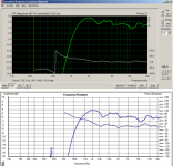
In the attachment I have compared the gain+phase between ARTA and HOLMImpulse (Imported wave-file impulse to ARTA)
In ARTA you will have to set time zero at the impulse peak - please refer to ARTA threads about this
The Next version of HOLMImpulse
All the features I've implemented have resulted in spaghetti code (Not to offend any Italians...)
I'm doing some code cleanup (Refactoring) at the moment so have some patience.
Attachments
Re: Cepstrum
In Wireless World Feb, March, May, 1982
Cepstrum Analysis by R.B. Randall and J. Heeaskbojesen said:Cepstrum domain
I actually implemented a cepstrum domain option/transformation, but I did not get any closer understanding much... The beauty of cepstrum domain is that the "cepstrum" in time domain can be direct multiplied instead of convolution, which is non-intuitive when we are far away from the driac.
The cepstrum is used when making minimum phase from a magnitude
(like HOLMImpulse > Analyze > QBox)
I might implement a minimum phase calculations from the magnitude instead of now using the impulse response to determine the phase - And such a calculation will utilize the cepstrum domain.
BUT singularities and other complex function theory complicationes did that I could not get a consistent and/or intuitive approach to the cepstrum. I might try again...
Does anybody have real measurement with a cepstrum which make them understand something new?
In Wireless World Feb, March, May, 1982
- Home
- Design & Build
- Software Tools
- HOLMImpulse: Measuring Frequency & Impulse Response