Hi ernesternest;
SSHV, If R1= 22 R, so CCS ~80mA
You get 40mA??
And not change V-out??
Thanks
Quanqhao,
It seems that if delta VDC shunt in minus VDC shunt out is too low, the current regulation stops working properly.
For example:
I have a 150VAC transformer, gives about 200VDC after rectification. My input 450R eats 20V, so I have 180 at the IRF9610. If I set the Vvoltage regulator to 160, it works properly until due to thermal drift Vout raises. When it reaches a certain value, shunt current starts to decline. Thats it.
Bringing down the Vout to a good value brings current back to the intended figure.
Rally hard to detect, at least for me
")
Cheers Ernst
No! good for Salas shunt in the DAC board, but it good for SSHV,
(4A, 600V STEALTHTM II Rectifier)
use :MUR140
Thanks
Thanks. But your BOM say 2A/800V and that number is only 1A/400v. Is half the value ok?
Thanks. But your BOM say 2A/800V and that number is only 1A/400v. Is half the value ok?
Yeah 1A is fine for the DAC board. I have some 11DQ10 (1.1A 100V) lying around so will use these.
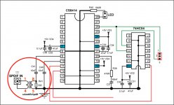
Have been getting the parts together for this DAC & having looked at the layout I think it is worth hardwiring the CS8412/4 loopfilter caps in a 'v' shape between pins 20 and 21. Anyone tried this?
Last edited:
Have been getting the parts together for this DAC & having looked at the layout I think it is worth hardwiring the CS8412/4 loopfilter caps in a 'v' shape between pins 20 and 21. Anyone tried this?[/QUOTE]
*** CS8412/4 loopfilter caps i**
You want say the layout have problem???
Thanks
*** CS8412/4 loopfilter caps i**
You want say the layout have problem???
Thanks
Can I change the IRF9540/540 to IRF9630/630?
no, 9540 and 540 is good!
Hi I have decided to get on and build Dac etc .
So i am filling in the pcb s and my relay is DS2Y 5V and has 8 pins but pcb has 10 holes plus a center one , can someone help please , have i got wrong one thanks john
hi! no problem!
you use it! 5v relay! or the sample!
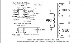
I'm also stuffing and soldering the board. A question on my SPDIF transformer. Here's the schematic.
1, 4 go to input. So 4 goes to + and 1 goes to - ?
5, 8 are the output so 5 to end of 75R that goes to coupling cap for receiver chip and 8 goes to opposite side of 75R?
1, 4 go to input. So 4 goes to + and 1 goes to - ?
5, 8 are the output so 5 to end of 75R that goes to coupling cap for receiver chip and 8 goes to opposite side of 75R?
Attachments
Last edited:
I'm also stuffing and soldering the board. A question on my SPDIF transformer. Here's the schematic.
1, 4 go to input. So 4 goes to + and 1 goes to - ?
5, 8 are the output so 5 to end of 75R that goes to coupling cap for receiver chip and 8 goes to opposite side of 75R?
Hi! im sorry,
you just plug it in it, with 1 and 4 are on.
so: 1 will be in print, the printer 4 to the GND (SPDIF)
5 are also connected to resistor R 75
thanks!
Sorry I don't understand. 4 goes to the neg of the input? 4 & 5 have the dot which I always thought goes to the +.
So, again, with that in mind is my question correct? The 75R side going to the cap has 5 on it and the other side has 8 on it.
BTW, this is a SMD device from Scientific. It doesn't plug in.
From a transformer site: "The dots tell you that when current is flowing "in" to the dot on the primary side, that current is also flowing "in" to the dot on the secondary side as well, or if current is flowing "out" on one side it is flowing "out" on the other side as well."
Last edited:
The pinout of the PCB is reference to Lundahl LL1572.
I think when you use the SC transformer, you better reconfig the pinout, that means, pin 1 to the GND of the SPDIF IN and pin 4(with dot) to the IN of the SPDIF IN, also the pin 5 to the input of the 0.01uF(C41), and the pin 8 to the output of the 0.01uF(C40)!
here attached the link of the Lundahl LL1572 for your reference
http://www.lundahl.se/pdfs/datash/1572_1573_1589.pdf
The pinout of the PCB is reference to Lundahl LL1572.
I think when you use the SC transformer, you better reconfig the pinout, that means, pin 1 to the GND of the SPDIF IN and pin 4(with dot) to the IN of the SPDIF IN, also the pin 5 to the input of the 0.01uF(C41), and the pin 8 to the output of the 0.01uF(C40)!
Thanks for the reference. But why wouldn't 8 go to the INPUT of C40. I guess I am confused.
If you look at the schematic of the Dac end.... According to that one leg of the input transformer goes to ground rail (on one side of the 75R resistor) and the other to input of C41. So pin 5 goes to C41 & pin 8 goes to ground? Right?
hi! you can see in the image!
Thanks
Or 1 to GND of Spdf. 4 to in
8 to GND, 5 to C41
Attachments
Last edited:
- Status
- This old topic is closed. If you want to reopen this topic, contact a moderator using the "Report Post" button.
- Home
- More Vendors...
- Quanghao Audio Design
- DAC-ASH (dac-end 2 up date)