Excellent !
Thanks for working on that Ian. I've been following this progress closely since I don't really want to try the more DIY effort at it referenced in this thread. Not comfortable with the precharging and such, but the gains at the implementation sound great. Currently, I get some glare in the treble hopefully this will tame.
Keep us posted on its availability. Seems to me we need 2 for a standard configuration like mine (RPI, LiFePO4, FiFoPi, ESS Controller, IVStd, Dual Mono 9038 HAT). I'll look again but I thought I have 3.3v for each DAC from the LiFePO4.
-Steve
Hello,
I need help solving a problem.with my LifePO4 board.
I have the message "short protection" after 10 seconds ON and i can't hear the sound of the relays.
I have A123 systems ANR26650M1-B 2500mAh batteries on BT6 BT7 BT2 BT5 BT9 BT3.
All batteries give 3,3 board OFF AND board ON.
All R015 resistors are OK.
If I unsolder all the batteries one by one, the problem remains.
If a remplace BT6 and BT7 (alone), the problem remains.
The board was working well, the problem appeared by connecting 2 supercapacitors on BT6 and BT7.
I loaded the supercapacitors from the LifePO4 board through a 3 ohm resistor, everything was OK.
I removed the load resistors, the supercapacitors were well charged but then impossible to make the LifePO4 work, the error message appeared.
How can I go further in my diagnosis?
Thanks.
nounouchet
Hi Ian,
I have a second LifePo4 board.
It runs with the same batteries.
Then there must be something wrong with that board...
I was very careful with the supercapacitors, they are soldered on a pcb with a triple terminal block: Pin1: GND; Pin2: 3.3V; Pin3: 3 ohms resistor to Pin2.
Could the current demanded by the supercapacitors have damaged the card?
nounouchet
ConditionerPi load transient response testing result
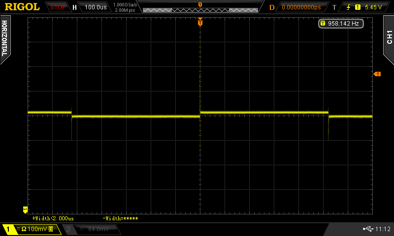
Again, the same load transient response test did to the new ConditionerPi. The active load set at demand current changing between 100mA to 1A every 500us. The 5V 3A power supply is a typical audiophile RPi linear power.
The first oscilloscope waveform shows the load response of the power supply only.
The second oscilloscope waveform shows the load response with ConditionerPi installed.
The third picture is the new ConditionerPi and linear power supply.
The improvement is very obviously. I use 8 BCAP0010 P270 X01 ultra capacitors for this test. The overall ESR was 10mOhm. The testing result is exactly as expected.
I heard there is a new ultra capacitor which is BCAP0010 P300 X11. I'm wondering if it could be better. I'll order some this weekend for next test.
ConditionerPi was designed to boost the 5V power supply quality for all RPi audio applications at local. I'll do more tests to different audio systems and DACs soon.

TypicalLinearPowerLoadResponse by Ian, on Flickr
LoadResponseWithConditionerPi by Ian, on Flickr

ConditionerPiWithLinearPower by Ian, on Flickr
Regards,
Ian
Again, the same load transient response test did to the new ConditionerPi. The active load set at demand current changing between 100mA to 1A every 500us. The 5V 3A power supply is a typical audiophile RPi linear power.
The first oscilloscope waveform shows the load response of the power supply only.
The second oscilloscope waveform shows the load response with ConditionerPi installed.
The third picture is the new ConditionerPi and linear power supply.
The improvement is very obviously. I use 8 BCAP0010 P270 X01 ultra capacitors for this test. The overall ESR was 10mOhm. The testing result is exactly as expected.
I heard there is a new ultra capacitor which is BCAP0010 P300 X11. I'm wondering if it could be better. I'll order some this weekend for next test.
ConditionerPi was designed to boost the 5V power supply quality for all RPi audio applications at local. I'll do more tests to different audio systems and DACs soon.
TypicalLinearPowerLoadResponse by Ian, on Flickr
LoadResponseWithConditionerPi by Ian, on Flickr
ConditionerPiWithLinearPower by Ian, on Flickr
Regards,
Ian
Last edited:
Again, the same load transient response test did to the new ConditionerPi. The active load set at demand current changing between 100mA to 1A every 500us. The 5V 3A power supply is a typical audiophile RPi linear power.
The first oscilloscope waveform shows the load response of the power supply only.
The second oscilloscope waveform shows the load response with ConditionerPi installed.
The third picture is the new ConditionerPi and linear power supply.
The improvement is very obviously. I use 8 BCAP0010 P270 X01 ultra capacitors for this test. The overall ESR was 10mOhm. The testing result is exactly as expected.
I heard there is a new ultra capacitor which is BCAP0010 P300 X11. I'm wondering if it could be better. I'll order some this weekend for next test.
ConditionerPi was designed to boost the 5V power supply quality for all RPi audio applications at local. I'll do more tests to different audio systems and DACs soon.
Regards,
Ian
any chance to adapt the conditioner-pi to beaglebone-black? 😉 converter pcb, manual hand wiring tips, etc.
best wishes
If I good understand the main goal of UcHybrid and ConditionerPi stuff is same, to reduce load transient response of linear psu. Base from the oscilloscope diagram I think that UcHybrid has better performance, but much practical ConditionerPi.Again, the same load transient response test did to the new ConditionerPi. The active load set at demand current changing between 100mA to 1A every 500us. The 5V 3A power supply is a typical audiophile RPi linear power.
The first oscilloscope waveform shows the load response of the power supply only.
The second oscilloscope waveform shows the load response with ConditionerPi installed.
The third picture is the new ConditionerPi and linear power supply.
The improvement is very obviously. I use 8 BCAP0010 P270 X01 ultra capacitors for this test. The overall ESR was 10mOhm. The testing result is exactly as expected.
I heard there is a new ultra capacitor which is BCAP0010 P300 X11. I'm wondering if it could be better. I'll order some this weekend for next test.
ConditionerPi was designed to boost the 5V power supply quality for all RPi audio applications at local. I'll do more tests to different audio systems and DACs soon.
Regards,
Ian
- Did you do comparative test?
- Do you think to use both of them?
- If yes did you do already listening test with both used?
Thank you
Gy.
If I good understand the main goal of UcHybrid and ConditionerPi stuff is same, to reduce load transient response of linear psu. Base from the oscilloscope diagram I think that UcHybrid has better performance, but much practical ConditionerPi.
- Did you do comparative test?
- Do you think to use both of them?
- If yes did you do already listening test with both used?
Thank you
Gy.
@Gy
Very good questions.
Actually ConditionerPi and UcConditioner are doing the same job but from different angle.
ConditionerPi belongs to RPi stack and improves the 5V RPi power quality directly to the local GPIO. While UcConditioner belongs to power supply and improves the quality external to RPi.
To use which one would be up to your applications. If you have a light weight RPi audio application, for example, a RPi DAC/streamer with normal 5V USB power supply, then the ConditionerPi would be the best solution to easily improve the sound quality right away at low cost. If you have a fully equipped project with high quality power supply such as LifePO4 battery power, then the UcConditioner would be your first choice.
The good thing is that the ConditionerPi and UcConditioner can work together to make the improvement even more. But I don't suggest doing so for the light weight projects.
Your are right, from the waveform, the ConditionerPi's performance looks not as good as UcConditioner. It was because that it has to use smaller ultra capacitors to fit the RPi stack space.However, ConditionerPi has an external ultra capacitor connector. If you really want, you can connect bigger external ultra capacitors to it to make the performance as same as UcConditioner.
Regards,
Ian
Last edited:
Thank you the detailed explanation, I'm very curious the rate of audible effect in both case.@Gy
Very good questions.
Actually ConditionerPi and UcConditioner are doing the same job but from different angle.
ConditionerPi belongs to RPi stack and improves the 5V RPi power quality directly to the local GPIO. While UcConditioner belongs to power supply and improves the quality external to RPi.
To use which one would be up to your applications. If you have a light weight RPi audio application, for example, a RPi DAC/streamer with normal 5V USB power supply, then the ConditionerPi would be the best solution to easily improve the sound quality right away at low cost. If you have a fully equipped project with high quality power supply such as LifePO4 battery power, then the UcConditioner would be your first choice.
The good thing is that the ConditionerPi and UcConditioner can work together to make the improvement even more. But I don't suggest doing so for the light weight projects.
Your are right, from the waveform, the ConditionerPi's performance looks not as good as UcConditioner. It was because that it has to use smaller ultra capacitors to fit the RPi stack space.However, ConditionerPi has an external ultra capacitor connector. If you really want, you can connect bigger external ultra capacitors to it to make the performance as same as UcConditioner.
Regards,
Ian
Again, the same load transient response test did to the new ConditionerPi. The active load set at demand current changing between 100mA to 1A every 500us. The 5V 3A power supply is a typical audiophile RPi linear power.
The first oscilloscope waveform shows the load response of the power supply only.
The second oscilloscope waveform shows the load response with ConditionerPi installed.
The third picture is the new ConditionerPi and linear power supply.
The improvement is very obviously. I use 8 BCAP0010 P270 X01 ultra capacitors for this test. The overall ESR was 10mOhm. The testing result is exactly as expected.
I heard there is a new ultra capacitor which is BCAP0010 P300 X11. I'm wondering if it could be better. I'll order some this weekend for next test.
ConditionerPi was designed to boost the 5V power supply quality for all RPi audio applications at local. I'll do more tests to different audio systems and DACs soon.
Regards,
Ian
If reclock has been used in the system, why we need to improve the power quality of RPi? It feels redundant to improve the power quality of the RPi, because the jitter from the RPi will be eliminated by reclock unless the reclock is poorly designed and using poor oscillator.
Thank you the detailed explanation, I'm very curious the rate of audible effect in both case.
I think it sounds the same.
If reclock has been used in the system, why we need to improve the power quality of RPi? It feels redundant to improve the power quality of the RPi, because the jitter from the RPi will be eliminated by reclock unless the reclock is poorly designed and using poor oscillator.
If you have sufficient resolution in your system you will most likely hear the difference. My hunch is it not the data integrity that is being improved here. It is the local RF environment. By that I mean everything that the player is connected to. RF behaves most inconveniently the higher up in frequency you go it gets everywhere. There are a LOT of high speed signals in the player, each has the potential to get somewhere it shouldn't and intermodulate with the audio. If the local RF environment can be improved by lowering power supply impedance and shortening the effective current loop it will make a difference.
The Pi is a noisy device, and not engineered as an audiophile device. Shared USB and ethernet bus, voltage DC switcher and such.
I have never seen any measurements, but after swapping a Pi 4 for an Allo USBridge sig I can hear that it is quieter I also added an Allo Shanti LPS .
I have never seen any measurements, but after swapping a Pi 4 for an Allo USBridge sig I can hear that it is quieter I also added an Allo Shanti LPS .
Last edited:
I should add that Ian will have followed good practice when designing the FiFoPi and DAC hats, and what I hear bears this out, but there are always lot of real world constraints that mean no design is ever perfect. If we could design the perfect DAC is would be a single impervious point in physical space, the power source would have zero impedance from DC to light under all conditions and have no electrical connection to anything 😀
I agree simon dart and misterdog. I believe it is noise in the Rpi that permeates everything. It is not the digital signal. The signal we listen to is generated in the FIFO. I give Rpi a separate PS and even separate path to ground. Even still, any improvement in power to the Rpi gives an improvement to the sound. Perhaps if we could take the signal to the FIFO via optical we'd improve. I believe there is some discussion on that topic on ecdesigns thread.
If reclock has been used in the system, why we need to improve the power quality of RPi? It feels redundant to improve the power quality of the RPi, because the jitter from the RPi will be eliminated by reclock unless the reclock is poorly designed and using poor oscillator.
Have a try and let us know if you hear an improvement? I'm sure most have a decent 5v PSU laying around.
AND if you are ok spending a bit more coin for an even better result, get an Allo USBBridge Signature.
Hi Greg!
I purchased at your recommendation USB Bridge Sig. Please give an advice what is the best way power the usbridge. I am thinking to use a linear power supply along with Uconditioner or ConditionerPi. What will be better for Ian boards (fifopi, es9038dual mono)?
Hi Greg!
I purchased at your recommendation USB Bridge Sig. Please give an advice what is the best way power the usbridge. I am thinking to use a linear power supply along with Uconditioner or ConditionerPi. What will be better for Ian boards (fifopi, es9038dual mono)?
Allo Shanti, it's a bargain. It even comes in a case 🙂
Claimed 0.08uV ripple.
Shanti Dual Linear Ultra Low Noise PSU
I power my USBridge Sig and my FIFO (via an LDO Reg) with it.
One of my 3.3V outputs from LiFeP04 has died so the 3 remaining power the dual mono DAC board .
- Home
- Amplifiers
- Power Supplies
- Develop ultra capacitor power supply and LiFePO4 battery power supply