This thread (and his brothers) is very singular: on the one hand there are the fundamentalist followers and on the other the extremist detractors.
Yunyun, what did you expect when you bought this devices? Did you expect SOTA devices?
If so then you were wrong.
Ian sells honest devices at affordable prices, I could say his devices have optimal quality-price ratio.
Think a while to his FIFO buffer (from the first version to FifoPi), it takes years of development to design these devices.
So the price is a bargain.
But if you are looking to SOTA audio devices, well, these are audio toys, very enjoyable toys, but always toys.
State of the art audio is another thing, and mostly another price level.
The FIFO buffer is a honest device that do its good job within the limits of its architecture.
You can't improve it to make it a state of the art device, but you can get it and enjoy for little money.
I think you are a little confused about: you have claimed that the Accusilicon are very good oscillators, and yes, you got them with a few bucks.
But you were absolutely wrong, the Accusilicon oscillators are very bad devices, and this is the reason you paid so little for them.
In comparison Ian's devices are far better than the Accusilicon you like so much.
If you are looking for a quality similar to the Accusilicon oscillators, you should thank Ian to offer better devices at honest prices.
But if you are looking for the best audio devices you have to spend much more.
So, back to the beginning, I think you have bought good devices for the price you paid, but don't expect to buy SOTA audio devices, it's not possible, they start a different price level, much higher than Ian's prices.
Just out of interest Andrea, what other FIFO buffer being sold today would you classify as SOTA?
Just out of interest Andrea, what other FIFO buffer being sold today would you classify as SOTA?
Andrea is developing his own FIFO which he suggests will be SOTA but at a corresponding price point. Sounds interesting ... time will tell. All power to him if he moves the bar higher. All credit to him to state with certainty that Ian has delivered amazing value to so many.
Andrea is developing his own FIFO which he suggests will be SOTA but at a corresponding price point. Sounds interesting ... time will tell. All power to him if he moves the bar higher. All credit to him to state with certainty that Ian has delivered amazing value to so many.
How was the Conditioning LED? What are the UCs you use on it? How did you measure the voltage?
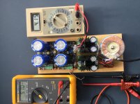
What's the power supply. Can you post a picture?
Ian
I use these power supplies from Tent labs: Tube heater supply
These power supplies are in use by me for years and they are very reliable and stable, I have also used a ps from a Samsung phone, same result. The ps is not to blame.
The voltage is measured on the pins between the two capacitors: J1
The capacitors are the types you advise: https://nl.mouser.com/ProductDetail/723-BCAP0325P270S17
There are two leds lighted: D8 and D5.
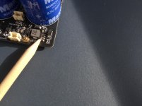
I have encountered another problem yesterday: one of the two modules that were working fine got a burned out transistor; U1, This happened while powering up again (after it was already conditioned and working) it was mounted on the Tentlabs ps.
All these problems have ocurred on the workbench, they did not get the chance to be mounted in the system.
So now 3 of the 4 delivered UcConditioners are not working.
This is all very disappointing, please help to fix it.
Attachments
Just out of interest Andrea, what other FIFO buffer being sold today would you classify as SOTA?
As far as I know not any on the diy circuit.
I have suggested several time in other thread what is the way to improve the efficiency of the FIFO buffer, but it seems that nobody was interested.
I suggested to slave the FIFO buffer to the DAC, I suggested to keep the FIFO far away from the Raspberry, but I see that new designs are all stacked. You cannot reach the best performance stacking the FIFO to the Raspberry since it generates a lot of EMI/RFI.
We are developing a SOTA audio system, from the source to the speakers, but since this is an hobby for us, it will take long time.
We are building the system for ourselves but we are glad to share our designs with the audio community.
SOTA oscillators are ready, maybe the best for digital audio ever.
Approaching digital audio the timing is crucial, so the best oscillators as possible is the starting point. Don't expect good performance using the CCHD-957, it's a toy.
The SOTA battery supply system is almost ready, we hope to share it in the new GB.
We are also developing a SOTA FIFO buffer, but it's very complex (2 chassis and several boards), so expect long time and it will be expensive.
In the meantime we are developing a Lite version of the FIFO
The Well synchronized asynchronous FIFO buffer - Slaved I2S reclocker
it shares the same architecture of the SOTA version with some compromises to get it more affordable.
Now we are developing and testing the firmware, we hope to share the design within a couple of months.
Here, it looks like that many people are thinking to get the performance of the MSB Tech devices (just to name one brand) taking from the shelf the Crystek oscillators and adding some cheap boards available on the diy circuit.
It's not so.
As I said several times you can get a CCHD-957 for a few Euros, but you get a bad oscillator. While you can get a SOTA oscillator from MSB, but you have to pay 19000 USD.
In the diy audio circuit you could get something similar to the SOTA devices on the market, but you cannot get them at the price of the Crystek, expect at least 10 times expensive and more.
The same for a FIFO buffer and so on.
how annoying to see these pasta long posts in other people's threads. maybe you just need to start doing like Ian. all these promises about measurements and superclocks have been going on since early spring - "here in two weeks" and again and again. but there are still no measurements to understand the difference between 5/6 and 11/12 and a doubler.
I have published the measurements, while others claim, promise but no measurement have been published.
It's increasingly difficult to maintain the discussion on a technical level.
But since I'm not interested in any fundamentalist battle, no problem, I'm sorry to annoying, I leave also this thread.
Bye
Andrea
Moreover nobody said you have to wait for my measurements, you are free to buy the Crystek and live happy with it.
Last edited:
I use these power supplies from Tent labs: Tube heater supply
These power supplies are in use by me for years and they are very reliable and stable, I have also used a ps from a Samsung phone, same result. The ps is not to blame.
The voltage is measured on the pins between the two capacitors: J1
The capacitors are the types you advise: BCAP0325 P270 S17 Maxwell Technologies | Mouser Nederland
There are two leds lighted: D8 and D5.
I have encountered another problem yesterday: one of the two modules that were working fine got a burned out transistor; U1, This happened while powering up again (after it was already conditioned and working) it was mounted on the Tentlabs ps.
All these problems have ocurred on the workbench, they did not get the chance to be mounted in the system.
So now 3 of the 4 delivered UcConditioners are not working.
This is all very disappointing, please help to fix it.
Hi Supersurfer,
Sorry about the issue. U1 is the pre-charger not the transistor. The only chance to damage it is that the input voltage is high than 6V. Even at short time. What was the output voltage of you power supplies?
I don't know Tentlabs ps, can I have more details about it. How did you power on/off it? What voltage did you set? If they are tube heat power supplies, the output voltage may not that stable.
I have used many power supplies with it, I never got problem. So if 3 of them have the same problems on your side, it should be some thing related.
I would suggest you trying the good one with a better 5V linear power supply to see if there is any problem.
To fix it is very easy. I'll send 4 chips to you to replace.
Regards,
Ian
Last edited:
I have published the measurements, while others claim, promise but no measurement have been published.
It's increasingly difficult to maintain the discussion on a technical level.
But since I'm not interested in any fundamentalist battle, no problem, I'm sorry to annoying, I leave also this thread.
Bye
Andrea
Moreover nobody said you have to wait for my measurements, you are free to buy the Crystek and live happy with it.
Andrea Take your time, the wait will be related to the result,
the caravan passes the dogs bark
")
Hi Supersurfer,
Sorry about the issue. U1 is the pre-charger not the transistor. The only chance to damage it is that the input voltage is high than 6V. Even at short time. What was the output voltage of you power supplies?
I don't know Tentlabs ps, can I have more details about it. How did you power on/off it? What voltage did you set? If they are tube heat power supplies, the output voltage may not that stable.
I have used many power supplies with it, I never got problem. So if 3 of them have the same problems on your side, it should be some thing related.
I would suggest you trying the good one with a better 5V linear power supply to see if there is any problem.
To fix it is very easy. I'll send 4 chips to you to replace.
Regards,
Ian
Hi Ian,
The U1 is burned out on one of the modules. Please sent a replacement chip for this one. I can replace it myself.
I do not have more information on the Tentlabs ps than the link in my post. They are also used by Tentlabs as a ps for a diy cd player. I have used them for powering raspberry pi and other stuff with no issues for years. I think they are very stable but I did not have a voltmeter connected when it browned out. It was adjusted to 5.0v, power on/of via a switch on 230v input. Maybe the switching of the UcConditioner itself has caused a voltage spike?
For the other two modules:
The power supplies are adjusted to 5.0v and I have turned one up to 5.2v to see if the charge is going up; and it did.
They have a charging issue and it is not related to U1 brown out. They will not charge higher than 4.10v with input of 5v. If I raise the input voltage 0.2v the charge will also raise. So I think it is a calibration issue or something similar.
How can this be solved?
Regards,
Last edited:
@Supersurfer
That's very strange. I never got UcConditioner problem with power supply as long as the PSU voltage is within UcConditioner working range.
Here is the example that my UcConditioner 5V and 3.3V work with LinearPi Dual (one set at 3.3V and the other keeps the default 5V). The finial charging voltages are almost the same as input voltages. And no matter how many times I turn on and off, there was no any problem. Once they are fully charge, it will go to conditioning stage immediately after it was turned on. LinearPi has built-in on/off management (in isolated mode). So in the setup two LinerPi work as a group with only one on/off switch. Thus, for better sound quality, AC power can be continuously connected to keep the capacitors always be charged.
LinearPi is a typical linear power supply, I don't think there is any difference from other linear PSUs except the 2.5A rated output current and the ultra low noise performance.
So, I'd be very interested in what was happened to your UcConditioner. I'll send the replacing parts to you tomorrow to see if you can fix them. If the problem happens again, you have to send the power supply to me to address the issue.

LinearPiDualUcConditioner2 by Ian, on Flickr

LinearPiDual1 by Ian, on Flickr
Regards,
Ian
That's very strange. I never got UcConditioner problem with power supply as long as the PSU voltage is within UcConditioner working range.
Here is the example that my UcConditioner 5V and 3.3V work with LinearPi Dual (one set at 3.3V and the other keeps the default 5V). The finial charging voltages are almost the same as input voltages. And no matter how many times I turn on and off, there was no any problem. Once they are fully charge, it will go to conditioning stage immediately after it was turned on. LinearPi has built-in on/off management (in isolated mode). So in the setup two LinerPi work as a group with only one on/off switch. Thus, for better sound quality, AC power can be continuously connected to keep the capacitors always be charged.
LinearPi is a typical linear power supply, I don't think there is any difference from other linear PSUs except the 2.5A rated output current and the ultra low noise performance.
So, I'd be very interested in what was happened to your UcConditioner. I'll send the replacing parts to you tomorrow to see if you can fix them. If the problem happens again, you have to send the power supply to me to address the issue.
LinearPiDualUcConditioner2 by Ian, on Flickr
LinearPiDual1 by Ian, on Flickr
Regards,
Ian
@Supersurfer
That's very strange. I never got UcConditioner problem with power supply as long as the PSU voltage is within UcConditioner working range.
Here is the example that my UcConditioner 5V and 3.3V work with LinearPi Dual (one set at 3.3V and the other keeps the default 5V). The finial charging voltages are almost the same as input voltages. And no matter how many times I turn on and off, there was no any problem. Once they are fully charge, it will go to conditioning stage immediately after it was turned on. LinearPi has built-in on/off management (in isolated mode). So in the setup two LinerPi work as a group with only one on/off switch. Thus, for better sound quality, AC power can be continuously connected to keep the capacitors always be charged.
LinearPi is a typical linear power supply, I don't think there is any difference from other linear PSUs except the 2.5A rated output current and the ultra low noise performance.
So, I'd be very interested in what was happened to your UcConditioner. I'll send the replacing parts to you tomorrow to see if you can fix them. If the problem happens again, you have to send the power supply to me to address the issue.
https://flic.kr/p/2jv4b8A
LinearPiDualUcConditioner2 by Ian, on Flickr
https://flic.kr/p/2jv8gnQ
LinearPiDual1 by Ian, on Flickr
Regards,
Ian
I received the parts from Ian yesterday and soldered them onto my UcConditioners. I even got a spare UcConditioner to test!
Everything is finally working now! I need to find the cause of the U1 browning out, the Tentlabs power supplies were never above 5,2v, and I have been using these for several years without any problems, maybe there was a power peak due to on/off switching.
I like the linearpi design and would like to get some of these the next time I am in the mood to order stuff from Canada.
Thank you Ian for your assistance through email and sending the parts!
How to order the LinearPI
The stacked LinearPi and UcConditioner is an obviously compact and elegant combination. Where can I get my hands on a couple of 5V LinearPis?
Like the look of the LinearPi, Ian. Will it be available in the latest group buy?
The stacked LinearPi and UcConditioner is an obviously compact and elegant combination. Where can I get my hands on a couple of 5V LinearPis?
Ian, is the difference between the solo and dual LinearPis that you can set the voltage of the dual LinearPi rails individually and therefor run 5v and 3.3v from one board?
LinearPi solo would have kelvin wiring so wouldn't you be able to feed two loads from one board (the difference being you can only output one voltage)?
Would you expect any sonic benefits to keeping all rails on a linear pi the same voltage or using a solo instead of a dual?
LinearPi solo would have kelvin wiring so wouldn't you be able to feed two loads from one board (the difference being you can only output one voltage)?
Would you expect any sonic benefits to keeping all rails on a linear pi the same voltage or using a solo instead of a dual?
This equation describes the voltage of the capacitor at any time. In other words, because the capacitance value of the supercapacitor is very large (denominator C), with the passage of time (numerator t), the change of the output voltage (Vc) can be suppressed, so the supercapacitor is indeed an ideal voltage source in theory. However, when observing the quality of power supply, you can’t just look at the theoretical voltage changes. Therefore, There is no way to explain that the super capacitor is an ideal power supply by provided the voltage measurement results. In fact, you still have to use your ears according to different usage scenarios. Listening can determine the most appropriate capacitance value. However, there is no relevant rule of thumb in the information provided by Ian.
Due to its own structure and material factors, the capacitor is equivalent to a circuit structure composed of C, L, and R, with a resonance frequency point. At this resonance frequency point, the capacitive reactance Zc of the capacitor is just equal to the inductive reactance Zl of the capacitor. The capacity of a capacitor is inversely proportional to its resonant frequency. The larger the capacity of the capacitor, the lower the resonant frequency, which means that the effective frequency range of the capacitor is smaller. Conversely, the smaller the capacity, the higher the resonance frequency and the larger the effective frequency range. When the frequency of the externally acting on the capacitor is higher than its resonant frequency, the capacitor is inductive, and when the frequency of the externally acting on the capacitor is lower than its resonant frequency, it is still capacitive.
Simply, the three factors of capacitive reactance, electrical impedance and inductive reactance will affect the frequency response, so the most ideal capacitor filter, that is, UcConditioner, which capacitor value is not just by a formula to confirm.
In short, Ian claims to be effective, and it may only be effective for a certain situation, but if a certain use condition changes, there will be far-reaching effects. In other words, Ian should be responsible for explaining the above-mentioned characteristics of UcConditioner, not just to make more money and cover up the innate characteristics of capacitor filters.
In fact, capacitor filters used in audio circuits often do not simply use a certain capacitance value, moreover, several capacitors with the same capacitance value are connected in parallel. However, Ian simply asked the user to install a 350F supercapacitor on UcConditioner without any guide? UcConditioner is really Ian's most irresponsible product in recent years.
Last edited:
I'm using 3 UcConditioners (5V version) to power my switches. I only use MaxWell supercap as Ian recommended in his instruction. We know each capacitor will have different sounding, so the same for supercapacitors. We should choose the right supercaps for our taste. Output wires in my UcConditioners are 14 awg solid copper (8 inches in length).
These UcConditioners are awesome in my system. They increase the dynamic (both macro and micro-dynamic), the sound has more weight in the full spectrum. These UcConditioners also improve the black background, thus sound layers are more separated. I love these UcConditioner.
In my opinion, to release the ability of our system, the first thing is equipment must have their own potential. For example, we couldn't see any improvement when we upgrade the whole power supply of a $100 CD player, but if we do the same power supply upgrading for a $1000 CD Player, then we could see the improvement of the upgrading.
One more instance is I have 2 same switches. One is modified in crystal and buck converter ICs. The other is just the stock one. I tried to put the UcConditioner to the stock switch but I didn't hear any different. When I use the modified switch, I hear some improvement over the stock one (of course without UcConditioner yet). After that, I add one UcConditioner to the modified switch, then the improvement is more. As in this experience, the UcConditioners are used in digital domain, which not alters the frequency spectrum. This is a perfect example to prove UcConditioner benefits.
To Ian: Thank you for your hard work. Please update the LinearPi status and information. I want to try it, Ian.
Last edited:
The LinearPi UsersManual was pushed this week, but pricing and ordering info not avail yet.
DocumentDownload/LinearPi at master * iancanada/DocumentDownload * GitHub
** Prices available on xls. Ordering info may not be accurate. Best to wait for official update.
32A LinearPi Solo linear power supply $59.00 $0.00 0
32A LinearPi Dual linear power supply $99.00 $0.00 0
33A LinearPi standoff/screw sets $4.90 $0.00 0
Last edited:
They increase the dynamic (both macro and micro-dynamic), the sound has more weight in the full spectrum. These UcConditioners also improve the black background, thus sound layers are more separated. I love these UcConditioner.
I think you describe very well the impact that many of us have found with supercaps added to the power supply.
For me it started with Greg in Mississipi delivering an in depth report on his sound preferences resulting from a wide range of Power supplies. His favorite by far was a pricey PS based on supercaps. I had a bunch of supercaps in my parts bin and tried adding them to my home grown linear supplies. I experienced an impact as described above. Various users reported similar experiences. Others said we were nuts. Ian has made it easy to safely take this route with UcConditioner. I don't know if there is a cook book for which cap will deliver the best sound in a given situation. Certainly many have been used and reported in this thread.
Ian, in a single LinearPi board, how many LT3045 regs are there? With 3A possible (below) does this mean there are 6 LT3045 regs on board?
@ Studley,
Just ran a quick test to LinearPi. Seems it's capable of 3A 5V output. The temperature just a bit higher than normal but still OK. And you have to make sure your transformer can delivery 3A current @AC 6V.
Ian
Last edited:
- Home
- Amplifiers
- Power Supplies
- Develop ultra capacitor power supply and LiFePO4 battery power supply