Would it degrade the direct battery power quality if i place a silicon diode in series with each of the three supply lines? ...
Immaculate work, have been following with interest. Also been wanting to know about the possibility of diodes and the affect of that?
Let me see if I get it right for my battery order:
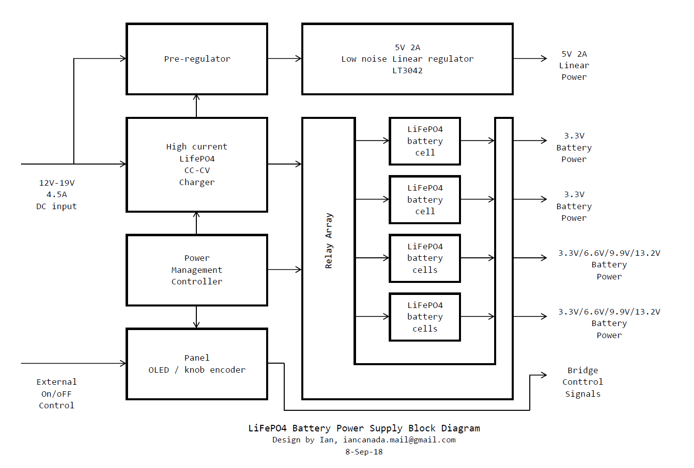
- Each board has four battery rails.
- So if each of them would have 3.3V, this means four batteries to buy...right ? Or did you configured the board so that you could use all the slots for batteries in any case, resulting in a higher capacity by paralleling batteries ?
If I want 26V: Possible with two battery rails in series (...for the CCS of my LTP-Tube stage) ?
Best Regards
Frank
Possible noob question below but just trying to figure out how many batteries to order!
")
Referring to the block diagram, I understand the first two rails are 3.3v only and they have just the one battery per rail required but I'm not clear on rails 3 & 4 which can each output 3.3V or 6.6V or 9.9V or 13.2V.
Does this mean that if I have the max 4 batteries in each of rails 3 & 4 and I select a 3.3V output on say rail 3, then are 3 of the 4 batteries (on rail 3) not used or are they configured into a parallel arrangement to give more capacity (for 3.3V)?
Thanks
Thanks Jesper,
That's a great idea. This kind of features have already been included in this LifePO4 power supply design.
If you listen to music for only two hours, normally the charge time will be 10 to 20 minutes. After that time, the charger will be stopped and goes into idle mode. The battery life will be extended comparing with charging it all the time.
The ending charge voltage is also under managed. If you just want to charge the cells to 3.35V, you can set it to. The charger will be stopped when the voltage level is reached. In this case, you can also set the sweet spot voltage according to your system and your preference on this power supply.
Regards,
Ian
Great thread. I thought my practical DIY experience might be of interest -
I started with A123 26650 LiFePO4 battery packs to power my music PC at 12.1VDC. [The 0.1 over 12.0 being to compensate for the inevitable losses in connectors/cables]. I use 3 packs of 4 batteries in parallel to lower ESR even further. So each battery cell is running at 3.0VDC well within the A123 spec.
I charge the battery packs with a good but not expensive linear power supply. Now the controversial point - I leave them float charging 24/7. The power usage is absolutely minimal as it is only keeping them topped up. They are of course ready to go, right on spec voltage all the time.
I know float charging batteries is frowned upon for introducing noise etc. but it is very easy to prove or disprove that point yourself with your ears, by listening to music and turning the PSU off and on and..... in my case I could discern no difference at all. My theory is that the enormous capacity of the LiFePO4 batteries effectively 'absorbs' any PSU noise introduced. I also believe that constant float charging, by keeping the batteries at constant voltage, there are no discharge/charge cycles and so they should last pretty much indefinitely. I am 2 years in with no ill effects.
The improvement in SQ was evident over the linear PSU on its own. And we are talking about the music PC here, not sensitive DACs etc. where the benefit should be even greater.
Part 2 - UltraCaps. I tried adding Maxwell 350F Ultracaps after the LiFePO4 battery packs all being constantly float charged by the linear PSU.
5 UltraCaps at their nominal specified 2.5V in series gives 12.0 - 12.5 VDC output. Perfect.
Some might say that's overkill, but for a reasonable outlay the Maxwell UltraCaps made a noticeable SQ improvement. Again with no empirical proof to present, my theory is the UltraCaps speed of reaction to the small but important peaks of current draw that playing music constantly calls for from a PSU, that distinguishes them from other PSU designs.
So Ian's definitely doing a fine professional job compared to my lo-tech amateur DIY approach and IMHO a combined LiFePO4/UltraCap PSU will be the best audio PSU you can produce bar none.
I bought a battery, from Taobao, which internal resistance is equivalent to A123 and the price is only half of A123. I bought 10 batteries and the test results were almost 5m ohms, each selling for 28.5 RMB (USD 4.14). 10 batteries are about 1kg which US shipping cost is for USD 53. However, the Taobao seller can’t send it abroad, so you have to find a way to handle international delivery.
26650????????3.2V???5800??A??????????-???


26650????????3.2V???5800??A??????????-???
Last edited:
No comments to this?Hi.
I would like to use LifePO4 battery supply for my TDA1541A DAC but the data sheet for TDA1541A says Max +/- 5,5V and - 16V with absolute max @ +/- 7V and -17V. LiFePO4 can supply +/- 6,6V and -16,5 V.
A little too close to the absolute max.
Has anyone tried this?
Would it degrade the direct battery power quality if i place a silicon diode in series with each of the three supply lines? That would lower the voltages to +/- 6V and -15,9V...
No comments to this?
The voltages you quote are for running the LiFePO4 batteries at their nominal 3.3V level.
I run mine at 3.0V (in four pack for 12V) and they work superbly; so you could lower your voltage to suit?
Personally, I try to avoid inserting any device in the battery supply circuit if at all possible, as they are likely to have a degrading effect and not a positive one.
Is it possible to run LiFePO4 @ 3,0 V? I thought one of the main features was a very little difference between a fully charged cell and a cell that needed recharging , and not near 10%? Woulden't you have to charge them very frequently to maintain only 3,0V?The voltages you quote are for running the LiFePO4 batteries at their nominal 3.3V level.
I run mine at 3.0V (in four pack for 12V) and they work superbly; so you could lower your voltage to suit?
Personally, I try to avoid inserting any device in the battery supply circuit if at all possible, as they are likely to have a degrading effect and not a positive one.
I too do not like the idea with a series component, but it is still a passive non-feedback element, so maybe not so degrading after all.
The other question is , would it be possible to run the TDA1541A so close to its absolute max. values?
You are right that the capacity of the batteries would be reduced at 3.0V compared to 3.3V. I float charge mine all the time, so that's not an issue for me.
Depends of course what load you are putting on the batteries. You could run more than one cell in parallel to up capacity (and reduce ESR).
Depends of course what load you are putting on the batteries. You could run more than one cell in parallel to up capacity (and reduce ESR).
You are right that the capacity of the batteries would be reduced at 3.0V compared to 3.3V. I float charge mine all the time, so that's not an issue for me.
Depends of course what load you are putting on the batteries. You could run more than one cell in parallel to up capacity (and reduce ESR).
I do not want to have a charger connected to the batteries while playing music, so that is not an option for me.
To measure the internal resistance of a battery below 10m ohms, you need to use a precision resistor to compare. For below 10m ohm of batteries, there is no simple and cheap way to measure.
First, measuring battery impedance at DC is of little value for audio. A battery with 50 milliOhm Z at DC may have impedance of 500 milliOhms at 10kHz. PSRR is thus severely compromised.
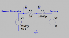
Second, measuring battery impedance does not require an expensive set up. The routine shown in Walt Jung's article "Regulators for High Performance Audio, Part 1" Figure 2c can measure impedance down to a single microOhm. A 1V sine signal through 20 ohms is sufficient (I pick 20R as that's the internal impedance of the AP Analyzer. (You don;t need an AP analyzer, just a sweep generator and scope with XY inputs). Sweep frequency from 10Hz to 1MHz
Attachments
First, measuring battery impedance at DC is of little value for audio. A battery with 50 milliOhm Z at DC may have impedance of 500 milliOhms at 10kHz. PSRR is thus severely compromised.
Second, measuring battery impedance does not require an expensive set up. The routine shown in Walt Jung's article "Regulators for High Performance Audio, Part 1" Figure 2c can measure impedance dotwn to a single microOhm. A 1V sine signal through 20 ohms is sufficient (I pick 20R as that's the internal impedance of the AP Analyzer. (You don;t need an AP analyzer, just a sweep generator and scope with XY inputs). Sweep frequency from 10Hz to 1MHz
Thanks jackinnj
I would be interested in trying this tester on my batteries but may need some help with it. Are you aware of any forum discussions that specifically discuss this battery impedance tester in diyaudio or elsewhere?
Thanks
I do not want to have a charger connected to the batteries while playing music, so that is not an option for me.
@koldby
Agree with you.
Float charging is fine for some applications that is not that serious. However, to reach top level performance, float charging method has some limitations:
1. If the battery is not fully charged, it will behave as shunt element, the charger will play the most important role to the power supply.
2. If the battery is fully charged, it will work like a decoupling capacitor. The direction of current to the battery will be switched rapidly between forward and backward. Noise will be generated. Chemical reaction will be changed in between.
3. Power supply can not be isolated from the charger or other related circuit.
In either case, the battery power supply performance will be degraded. No longer as good as pure battery power. It will be the same story to the ultra capacitor power supply with float charge scheme.
Regards,
Ian
Have you ever tried to put a silicon diode in series with the batteries to see (hear) what impact it has on sound quality (if any)?@koldby
Agree with you.
Float charging is fine for some applications that is not that serious. However, to reach top level performance, float charging method has some limitations:
1. If the battery is not fully charged, it will behave as shunt element, the charger will play the most important role to the power supply.
2. If the battery is fully charged, it will work like a decoupling capacitor. The direction of current to the battery will be switched rapidly between forward and backward. Noise will be generated. Chemical reaction will be changed in between.
3. Power supply can not be isolated from the charger or other related circuit.
In either case, the battery power supply performance will be degraded. No longer as good as pure battery power. It will be the same story to the ultra capacitor power supply with float charge scheme.
Regards,
Ian
Have you ever tried to put a silicon diode in series with the batteries to see (hear) what impact it has on sound quality (if any)?
@koldby,
I didn't do it this way. But I think it worth to give a try.
The only thing I concern about is the possible noise from a diode. What I would suggest is that put a capacitor in parallel with the diode to bypass any possible noise. Please let me know if you have any update.
Regards,
Ian
First, measuring battery impedance at DC is of little value for audio. A battery with 50 milliOhm Z at DC may have impedance of 500 milliOhms at 10kHz. PSRR is thus severely compromised.
Second, measuring battery impedance does not require an expensive set up. The routine shown in Walt Jung's article "Regulators for High Performance Audio, Part 1" Figure 2c can measure impedance down to a single microOhm. A 1V sine signal through 20 ohms is sufficient (I pick 20R as that's the internal impedance of the AP Analyzer. (You don;t need an AP analyzer, just a sweep generator and scope with XY inputs). Sweep frequency from 10Hz to 1MHz
Is the measurement method you mentioned more expensive? The measuring instrument I mentioned earlier was bought, from Taobao, for only USD $18.
Measuring the internal resistance of the battery is only to determine the battery that is purchased, especially the battery of an unknown brand. Whether it is worth buying, it is not really necessary to determine the true internal resistance of the battery.
Last edited:
Thanks jackinnj
Are you aware of any forum discussions that specifically discuss this battery impedance tester in diyaudio or elsewhere?
Thanks
Read the articles by Walt Jung, the guru -- the referenced articles are very easy to find on the web.
Omicron's Bode-100 -- application note: https://www.omicron-lab.com/fileadm...impedance/App_Note_Battery_Impedance_V2_0.pdf
First, measuring battery impedance at DC is of little value for audio. A battery with 50 milliOhm Z at DC may have impedance of 500 milliOhms at 10kHz. PSRR is thus severely compromised.
Second, measuring battery impedance does not require an expensive set up. The routine shown in Walt Jung's article "Regulators for High Performance Audio, Part 1" Figure 2c can measure impedance down to a single microOhm. A 1V sine signal through 20 ohms is sufficient (I pick 20R as that's the internal impedance of the AP Analyzer. (You don;t need an AP analyzer, just a sweep generator and scope with XY inputs). Sweep frequency from 10Hz to 1MHz
Is the measurement method you mentioned more expensive? The measuring instrument I mentioned earlier was bought, from Taobao, for only USD $18.
Measuring the internal resistance of the battery is only to determine the battery that is purchased, especially the battery of an unknown brand. Whether it is worth buying, it is not really necessary to determine the true internal resistance of the battery.
Cheap is, as cheap is.
Read the articles and learn.
- Home
- Amplifiers
- Power Supplies
- Develop ultra capacitor power supply and LiFePO4 battery power supply