Here is a all-in-one solution for your application, and you can use a much better (quieter) regulator, like I suggested in post #137 of the thread.Also this psu will be for a class A headphone amp. Should i bother to add an lm317 regulator after it or will it be detrimental in terms of noise?
GB for Simple Cap-Mx Regulated Low-Noise PSU
I would not add a linear regulator to the output unless you needed the voltage regulation. It will add extra heat due to the voltage drop of the regulator and will limit the current (which may or may not help your end goal). Also, Cmx circuit is similar to how a linear regulator is built with discreet components, and it can be modified to provided voltage regulation if you wanted to go that route.
I rather like the idea of voltage regulator after capacitance multiplier, myself. It's a straightforward way to improve (2 x fmains) PSRR by 40dB, compared to a voltage regulator all by itself. The upstream CM also removes plenty of treble and HF noise, making the downstream voltage regulator's job that much easier. And don't forget, if your voltage regulator is protected against overcurrent, as VREG ICs are, a short to ground isn't a catastrophe of component failures. CM followed by CM is unprotected and likely to fail if the output becomes shorted to ground.
Have a look at this option:but for class a, i was told cmx is the way to go
The SLB (Smooth Like Butter) Active Rect/CRC/Cap Mx Class A Power Supply GB
you cant diy it for less than this:
SUNYIMA LM317 LM337 Filter Regulated Voltage Power Supply Board Adjustable Continuous For Preamp Headhpone AMP DIY KITS|power adjuster|power supply adjustablevoltage regulator adjustable - AliExpress
if you like it, you can upgrade the caps later.
SUNYIMA LM317 LM337 Filter Regulated Voltage Power Supply Board Adjustable Continuous For Preamp Headhpone AMP DIY KITS|power adjuster|power supply adjustablevoltage regulator adjustable - AliExpress
if you like it, you can upgrade the caps later.
Hi, I have read all the 3d but I can't find anywhere on the net, in any language, how to calculate, size, a capacity multiplier using an IRF840 mosfet.
Do you have a scheme to provide me? Unfortunately, I can't use your beautiful pcbs due to their size and more.
I would like to use this scheme because it seems to me that it has excellent filtering. I see two RC cells for which I imagine filters more!
The values are random. What values should I use and how are they calculated?

Are CX and CY necessarily required?
Wouldn't it be better to have a 1K R as a gate stopper?
I know the formula to find the cut-off frequency (Ft = 1 / (2 * 3.14 * R * C) as I know, more or less, how it works.
I don't know how the current I am going to absorb affects the calculations. the supply voltage upstream.
I know I have to guarantee a voltage drop of, say, about 4v to make sure the circuit does its job.
I would like to build two capacitance multipliers for two anode voltages.
The first is about 300V and 3-4mA of load, the second of 180 / 200v with 20 / 22mA of load.
The multipliers are at the end of the anodic "power line", immediately before the valves and after everything else, ie straightening, leveling and stabilization I would go and put them for a further "file" to the remaining ripple which is obviously already low, but I would like to reduce it to a minimum as it is a preamp for MM / MC cartridges.
I apologize if I have dwelt on writing.
Thanks for any help.
Do you have a scheme to provide me? Unfortunately, I can't use your beautiful pcbs due to their size and more.
I would like to use this scheme because it seems to me that it has excellent filtering. I see two RC cells for which I imagine filters more!
The values are random. What values should I use and how are they calculated?
Are CX and CY necessarily required?
Wouldn't it be better to have a 1K R as a gate stopper?
I know the formula to find the cut-off frequency (Ft = 1 / (2 * 3.14 * R * C) as I know, more or less, how it works.
I don't know how the current I am going to absorb affects the calculations. the supply voltage upstream.
I know I have to guarantee a voltage drop of, say, about 4v to make sure the circuit does its job.
I would like to build two capacitance multipliers for two anode voltages.
The first is about 300V and 3-4mA of load, the second of 180 / 200v with 20 / 22mA of load.
The multipliers are at the end of the anodic "power line", immediately before the valves and after everything else, ie straightening, leveling and stabilization I would go and put them for a further "file" to the remaining ripple which is obviously already low, but I would like to reduce it to a minimum as it is a preamp for MM / MC cartridges.
I apologize if I have dwelt on writing.
Thanks for any help.
Last edited:
I am interested in this pcb. A couple of days ago I have seen it on PC way site offered for purchase.Yes, its a 15mm pitch alright, plus now I have put some options for 5mm and 10mm just in case someone wants to use something else.
you can order boards yourself. attached are the gerbs and stuffing guide , also pdfs in case someone wants to etch at home.
Let me know if you have any problems with boardhouse with these gerbers, I can clarify / use older method. I have now moved over to eagle 9.0.0, pcbway didnt like those 9.0.0 gerbers initially. Now its settled with them
Top plane is a ground plane thats only connected at output.
regards
Prasi
edit: logos are on the bottom silk, so don't affect the functionality or beauty of top silk
Here is additional info.
Can somebody say whether that board is the most recent or there is a new version available elsewhere?
Thanks
Thanks for the info Prasi and for your contribution to this conversation. I do indeed appreciate that.the one on PCBway is with on board rectifiers.
The quoted post is without rectifiers. (external chasis mount rectifiers)
both are good.
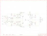
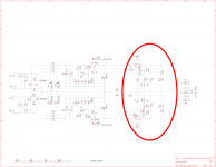
Prasi is kindly helping me design a CRC->MX PCB with an adjustable regulator circuit on the end, quite simply a tracking pre-reg circuit with the MX as pre regulator and the LMXX7 adjustable section on the output.
My question is - in the schematic attached below, is there any need for the original VR1 & VR2 1K trimmers? Can these be replaced by fixed resistor or just omit all together.
Normally, the 1K trimmers only adjust by a volt or so to fine tune the rails. Maybe this will still be useful.
Thinking about it - the MX section can be trimmed first before VR7 & 8 are installed, then install the other trimmers for final voltage adjustment but having four expensive trimmers seems a bit much.
It would be nice to remove VR1 & 2 entirely.
Attachments
Hi Passive,
The CapMx pots adjust the voltage dropout for ripple reduction. If you will use this psu for various applications, I’d think you would want to keep this adjustment for different current demands.
Nice Psu!! Looking forward to your progress
My 2 cent suggestion, add redundant rectifier pads for Prasi’s SMD LT4320 Ideal Bridges
Last edited:
re: post #814 schematic
It's surprising that you've chosen diodes (MSR860) which are only available in thru-hole packages, while at the same time using bipolar transistors (BCP53, BCP56) which are only available in surface mount packages. Since the big electrolytic capacitors are definitely going to be thru-hole, and so are the discrete power transistors + heatsinks, there's no question: you WILL have several thru hole parts on the board. Given that, why also select the surface mounted BCP53? Does it have characteristics & properties that are simply unavailable in thru hole parts?
Curiously, R1-double-prime and R2-double-prime do not have "solder dots" on that schematic. Is this anything to be concerned about?
Vunce and Mark, thank you for the replies boys.
Vunce - good to know, that's what I wanted, we'll leave them in. Yes, hopefully a nice PSU, this was born out of a previous design Prasi did. See below.
Good idea on the redundant pads.
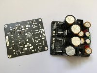
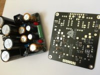
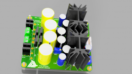
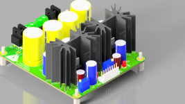
Mark - the MSR860's were just used by Prasi to construct the circuit, I may ask for D041 parts but initially this was born out of an idea I had to incorporate the LT4320 bridge with the SMD MX circuit, I wanted a higher power version of the mini SMD board on here. See pics below.
The circuit is LT4320->CRC->MX which works fantastically, lovely supply with very low dropout. Unfortunately the built supply in the pic cost around £70! Waaayyy too expensive. But a nice design.
So I wanted the mid power SMD design with a more reasonable bridge and more adjustability. The BCP transistors were inherited from the SMD design but uprated to SOT223-3 packages.
Not sure about the R1/R2 solder dots, will inform Prasi.
Vunce - good to know, that's what I wanted, we'll leave them in. Yes, hopefully a nice PSU, this was born out of a previous design Prasi did. See below.
Good idea on the redundant pads.
Mark - the MSR860's were just used by Prasi to construct the circuit, I may ask for D041 parts but initially this was born out of an idea I had to incorporate the LT4320 bridge with the SMD MX circuit, I wanted a higher power version of the mini SMD board on here. See pics below.
The circuit is LT4320->CRC->MX which works fantastically, lovely supply with very low dropout. Unfortunately the built supply in the pic cost around £70! Waaayyy too expensive. But a nice design.
So I wanted the mid power SMD design with a more reasonable bridge and more adjustability. The BCP transistors were inherited from the SMD design but uprated to SOT223-3 packages.
Not sure about the R1/R2 solder dots, will inform Prasi.
Attachments
I'm looking for a -+12V and -+5V dual rail PS and I really like the "Nice 4 cap Mx on 100mm square PCB by Prasi" in the first post *but* I want to have tight regulation (I'm feeding dac chips).
There are a million different designs in this thread so if I missed the one fitting my needs I apologize
I was wondering if I could just 'paste' the LMXX7 regulator part from passive420's design in post 814 on the output of Prasi's design. (see attached pic)
There's some discussion here about if adding a regulator after the Cx is a good idea and I didn't see a real answer to this.
This, Simple Cap-Mx Regulated Low-Noise PSU, looks good but like I mentioned, I also need negative rails.
Attachments
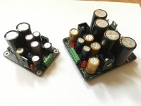
Cool Jazz, the boards with extra LM reg section have been ordered, I'll let you have a couple when they arrive.
They have option for the SMD LT4320 bridge PCB's as well as TO-220 diodes. These will be excellent supplies I think.
Awesome work by Prasi.
They have option for the SMD LT4320 bridge PCB's as well as TO-220 diodes. These will be excellent supplies I think.
Awesome work by Prasi.
Attachments
Last edited:
- Home
- Amplifiers
- Power Supplies
- Juma's Easy-Peasy Capacitance Multiplier