Nice work Prasi! Now mirror second one with complementary parts for -ve rail on same 100mm x 100mm board? I guess we need schematic from designer mark Johnson...
Nice work Prasi! Now mirror second one with complementary parts for -ve rail on same 100mm x 100mm board? I guess we need schematic from designer mark Johnson...
thanks x, I will make an attempt at the neg rail tonight and put it here for comments.
regards
Prasi
Can someone please delete the above post. It was a mistake while trying to edit the post.
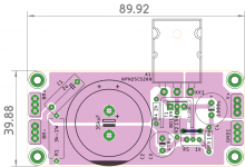
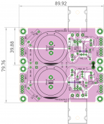
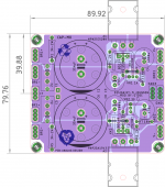
Here is the dual rail version with negative rail with PNP devices. Can someone take a look and suggest changes?
Rail grounds are separated. J3 can be used to connect gnds of + and - rails at the o/p. J1, J2 better jumpered from the bottom or use insulated wire.
If required, PCB can be cut right down the middle, to use + or the - rail 😀
regards
Prasi
Attachments
Last edited:
Great layout as usual Prasi! I’m guessing it took you an order of magnitude less time to compete than me, very impressive 🙂. The layout of the transistors with an extra heatsink makes for nice and clean routing.
What do you mean by this? Does this refer to how the ground plane is routed vs mine?
I did not investigate a dual rail version of this since I am looking to place this after a single rail SMPS and have very limited space to work with in my MoFo build. I think next steps I’ll send out my layout for fabrication and see what happens!
referenced the grounds to o/p.
What do you mean by this? Does this refer to how the ground plane is routed vs mine?
I did not investigate a dual rail version of this since I am looking to place this after a single rail SMPS and have very limited space to work with in my MoFo build. I think next steps I’ll send out my layout for fabrication and see what happens!
Thanks gtose.
By referencing the grounds to o/p means all the grounds are connected to the o/p ground of Cap-Mx. except ofcourse C1 and R1. It is done for lower noise , it was suggested by jameshillj on this very thread somewhere.
All the best for your test.
regards
Prasi
By referencing the grounds to o/p means all the grounds are connected to the o/p ground of Cap-Mx. except ofcourse C1 and R1. It is done for lower noise , it was suggested by jameshillj on this very thread somewhere.
All the best for your test.
regards
Prasi
By referencing the grounds to o/p means all the grounds are connected to the o/p ground of Cap-Mx. except ofcourse C1 and R1.
I'm still confused about o/p. Sorry, but I'm still a rookie and trying to follow.

Excellent work, though.
.
I'm still confused about o/p. Sorry, but I'm still a rookie and trying to follow.
Excellent work, though.
.
e.g. R4 & C3 grounds are connected to o/p faston 'GND1', rather than C2 ground. Catch my drift?
Then perhaps try it, hope you find the love, lasting after you tried it in a class a amplifier.
Reason we do for love are sometimes irrational but worth it.
Reason we do for love are sometimes irrational but worth it.
e.g. R4 & C3 grounds are connected to o/p faston 'GND1', rather than C2 ground. Catch my drift?
Not really... But after I Googled "o/p electronics", I gathered that you mean "output". 😱
Now I know.

Last edited:
Not really... But after I Googled "o/p electronics", I gathered that you mean "output". 😱
Now I know.
 Not a standard shortform, but somehow a part of written jargon here in India. I should be more careful.
Nice work, Prasi.
I would love to try this for a Class A Alpha amp.
I will merge the grounds of +/- rails and send you the gerbers. let me know if you have any specific component package for C1.
regards
Prasi
Hey Prasi, don't beat yourself over it. I should have been clearer that it was the "o/p" acronym that I didn't understand.
You're doing great work as usual, and I didn't mean to discourage you. 🙂
We are too lucky that we have you here Prasi!
You are a very generous gentleman.
Best Regards.
Thimios.
You are a very generous gentleman.
Best Regards.
Thimios.
I will merge the grounds of +/- rails and send you the gerbers. let me know if you have any specific component package for C1.
regards
Prasi
Thanks for doing this and what you have is fine - I will make it fit. I typically use 15mm pitch MKT radial so I think looks close to what you have there. If you have any plans on making boards yourself I can buy them from you. But I probably have upcoming PCB orders in the works and this is a good “add-on” order once you have shipping covered.
Thanks for doing this and what you have is fine - I will make it fit. I typically use 15mm pitch MKT radial so I think looks close to what you have there. If you have any plans on making boards yourself I can buy them from you. But I probably have upcoming PCB orders in the works and this is a good “add-on” order once you have shipping covered.
Yes, its a 15mm pitch alright, plus now I have put some options for 5mm and 10mm just in case someone wants to use something else.
you can order boards yourself. attached are the gerbs and stuffing guide , also pdfs in case someone wants to etch at home.
Let me know if you have any problems with boardhouse with these gerbers, I can clarify / use older method. I have now moved over to eagle 9.0.0, pcbway didnt like those 9.0.0 gerbers initially. Now its settled with them 😉.
Top plane is a ground plane thats only connected at output.
regards
Prasi
edit: logos are on the bottom silk, so don't affect the functionality or beauty of top silk😀
Attachments
Last edited:
We are too lucky that we have you here Prasi!
You are a very generous gentleman.
Best Regards.
Thimios.
Thanks man. I have posted diy version pdfs or you could get a couple of nice double sided pcbs from xrk.
regards
Prasi
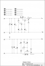
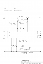
Thank you, Prasi. Looks great. The schematic shows the star GND hub as the Common bridge input. Should the star hub be located at the output GND pin? The actual layout appears to have the GND output connected to the big top GND plane, so maybe it doesn't matter.
X
X
Yes, it doesnt matter. Sch is just showing connections/nets. On the layout however, all the action is at the output.
- Home
- Amplifiers
- Power Supplies
- Juma's Easy-Peasy Capacitance Multiplier