Well, it's finally done. Attached are photos of my boards, but I have some questions…
The AC voltage dropped from 15-12 mV to just at 1mV, as measured by a Fluke 87 V I borrowed from work. Even with the Fluke's leads shorted, the lowest it measured was 0.2mV The 1mV was measured with everything powered up and running, music turned up a little, but not a lot. Is that good enough? 8)
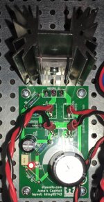
The power supply had sufficient range to get the output power out back up to 24v. The only concern is the heat sinks. They are huge, but still get to 70C in open air and to 79/80C with the lid on. How much of a concern is that? With them passing just 1.5A, I believe they are still well within the de-rate line. They are lined up immediately under the vent slots on the lid for maximum passive cooling.
If I was starting over again, I would scoot the ACAs MOSFETs down enough to bolt the Cap-Mult MOSFET to the monster heatsink. Perhaps I will do so later. The fins only get to 45 at the base and much lower at the tips (2U 300mm deep dissapante case).
The AC voltage dropped from 15-12 mV to just at 1mV, as measured by a Fluke 87 V I borrowed from work. Even with the Fluke's leads shorted, the lowest it measured was 0.2mV The 1mV was measured with everything powered up and running, music turned up a little, but not a lot. Is that good enough? 8)
The power supply had sufficient range to get the output power out back up to 24v. The only concern is the heat sinks. They are huge, but still get to 70C in open air and to 79/80C with the lid on. How much of a concern is that? With them passing just 1.5A, I believe they are still well within the de-rate line. They are lined up immediately under the vent slots on the lid for maximum passive cooling.
If I was starting over again, I would scoot the ACAs MOSFETs down enough to bolt the Cap-Mult MOSFET to the monster heatsink. Perhaps I will do so later. The fins only get to 45 at the base and much lower at the tips (2U 300mm deep dissapante case).
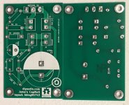
Attachments

You could easily just attach them to the main heatsinks towards the back beside the power amp boards and this allows for shorter cables too - could lift the audio input signal wires well above the re-located CMx to avoid any possible 'noise' transfer
The heat generated by the C-Mx is basically 'VxI' so this is about 4.5v (volts across the fet) x 1.5A (guessing the current thru the ACA) = approx 7watts and on the main heatsink, this won't make much difference but will keep the fet much cooler
You don't really need the big cap on the o/p of the C-Mx as there's a big cap already on the ACA board - just saying ...
That 'switcher supply' makes the assembly very simple
Or even bend the legs on IRFp240 90 degrees and mount underhung with thermal contact to the steel bottom panel. It’s probably enough for 5-7w dissipation.
I don’t recall ACA having on board rail smoothing cap, big one is output coupler. So leave the one in the cap Mx board. Mounting on 2U heatsink is adding probably 7w too much heat load as that one is at about the limit of 35w already (~1.5amp x 24v). I have 4U and it has about 75w limit.
I don’t recall ACA having on board rail smoothing cap, big one is output coupler. So leave the one in the cap Mx board. Mounting on 2U heatsink is adding probably 7w too much heat load as that one is at about the limit of 35w already (~1.5amp x 24v). I have 4U and it has about 75w limit.
Last edited:
two of something like these perhaps , as plenty of space is available on either side of smps
New 60*150*25mm Cooler Aluminum Heatsink Heat Sink Chip for IC LED High Power Transistor -in Fans & Cooling from Computer & Office on Aliexpress.com | Alibaba Group
It can be placed horizontally and check the temperature or vertically too as width is 60mm and will fit in 2U chassis. Vertical placement would provide plenty of cooling and can be screwed to mounting plate.
Last edited:
+1 in Prasi’s recommendation. In fact, I used exact same heatsink on mine and it works in Class A at 1.35amps ea MOSFET and two per heatsink or about 12w per sink.
+1 in Prasi’s recommendation. In fact, I used exact same heatsink on mine and it works in Class A at 1.35amps ea MOSFET and two per heatsink or about 12w per sink.
Aha! Alpha20, I guess.
All the best with big boy too... Are you planning to use the same CMX for big boy too? or plain old CRC and switcher?
may be too much heat from CMX if used with big boy?
Hi Prasi,
Alpha Big Boy (52w) is running on traditional 400VA linear trafo and CRC-CRC as current is 3amps and rails are +/-35v. It’s running beautifully - zero adjustments and bias is rock stable and DC offset is 0mV to 8mV from cold to hot. Here is channel 2 just fired up. Now need to make another PSU before I can listen in stereo.
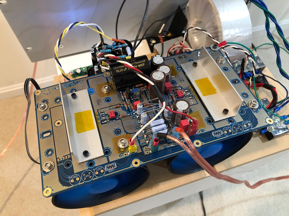
No scary heat or temps at all. “feels like a 50w Class AB” amp since temps at MOSFET body are 37C and heatsink fins are 27C. Fans at minimum 10% speed for quiet operation.
Alpha Big Boy (52w) is running on traditional 400VA linear trafo and CRC-CRC as current is 3amps and rails are +/-35v. It’s running beautifully - zero adjustments and bias is rock stable and DC offset is 0mV to 8mV from cold to hot. Here is channel 2 just fired up. Now need to make another PSU before I can listen in stereo.
No scary heat or temps at all. “feels like a 50w Class AB” amp since temps at MOSFET body are 37C and heatsink fins are 27C. Fans at minimum 10% speed for quiet operation.
Thanks james for your prompt reply. Ill try bypass for my next build and report my findings.
Also are the mosfets specified in the first schematic the best choice? How about latfets or darlingtons? I wouldnt mind spending lil extra to get the most out of this simple circuit
Also are the mosfets specified in the first schematic the best choice? How about latfets or darlingtons? I wouldnt mind spending lil extra to get the most out of this simple circuit
If you just need to have ripple control the best are the IRFP240 9240 from value standpoint. They are designed for this type of power regulation and handle up to 20amps when heatsinked properly. If you want more current by the IRFP250/9250 - basically double current. If you can look for lower Vgs MOSFETs you have lower dropout voltage.
Thanks XR for the info about that output cap - good one, saves much embarrasment - love seeing that thermistor attached to the central 0 volt point
Donovas, there's a lot of different transistors used in this type of circuit and you have to look at each ones 'ad + dis' advantages - for example, units like the TeddyRegs use the D44/45H11 with a driver fet/transistor in the Siklai o/p arrangement but it's designed to be a 'complete' regulator, the K-multiplier uses a similar transistor with a bc *** driver (a filter/impedance/low component, smart circuit), the AMB (much copied from China) is a regulator but can be simplified to a high gain CMx - it uses the IRFZ24/IRF9Z34N pair with bc *** drivers, and so on.
The bottom line is the old saying 'it depends' on how much trouble you want to go to and what results are required - the often use of the IRFP240/9240s is that many folks have a lot of them hanging around, they're tough buggers, relatively cheap and the drop of 4.5 volts across the devices are just a challenge!
I think I mentioned it before but have a readup of the 'K-multiplier' website - it offers great explanations of how this simple circuit operates in different arrangements and Prasi has done some recent pcb designs with this cct in mind too - options ...
You could easily just attach them to the main heatsinks towards the back beside the power amp boards and this allows for shorter cables too - could lift the audio input signal wires well above the re-located CMx to avoid any possible 'noise' transfer
The heat generated by the C-Mx is basically 'VxI' so this is about 4.5v (volts across the fet) x 1.5A (guessing the current thru the ACA) = approx 7watts and on the main heatsink, this won't make much difference but will keep the fet much cooler
That 'switcher supply' makes the assembly very simple
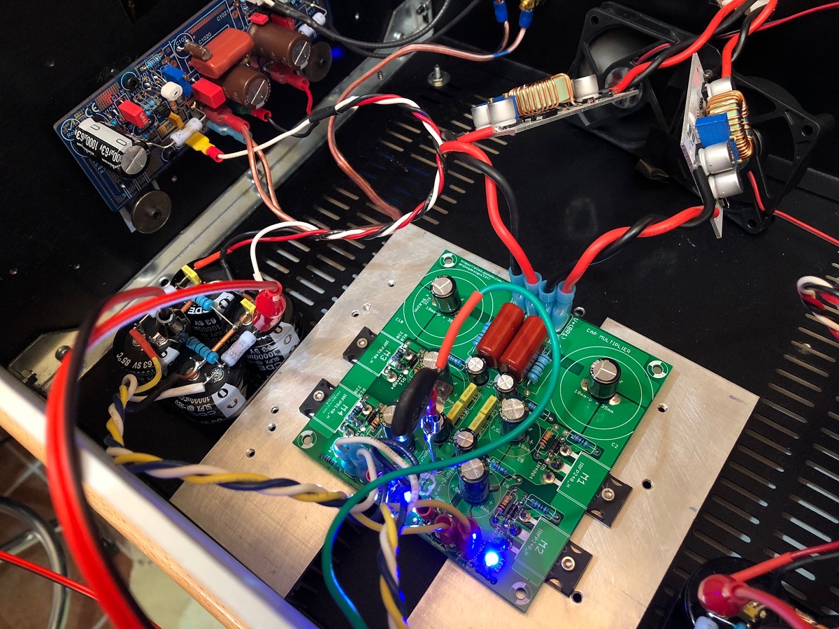
To make room on the main heat-sinks, I would have to rearrange (ie re-drill) the holes). For me, this isn't a big issue, as I have the MOSFETs on short wires, so I'd probably move the ACA boards to the baseplate and mount just the heat generators to the heat-sink.
Based on basic heat generated (and current leaving the circuit to go thru the speaker instead of the amplifying device), I'd split the heat sink about 1/6 for the CapMult device, 1/2 for the constant current device and the remaining 1/3 for the amplifying device. When the music is quiet, the amp device will be a little warmer, but the louder you play it, the better off it will be (heat wise). 8)
Or even bend the legs on IRFp240 90 degrees and mount underhung with thermal contact to the steel bottom panel. It’s probably enough for 5-7w dissipation.
I don’t recall ACA having on board rail smoothing cap, big one is output coupler. So leave the one in the cap Mx board. Mounting on 2U heatsink is adding probably 7w too much heat load as that one is at about the limit of 35w already (~1.5amp x 24v). I have 4U and it has about 75w limit.
These devices are already underhung (the individual heat sinks are 2.5" tall!!), but I have plenty of heat capacity, as I got the 300mm deep case, not the stock 200mm deep one. That and I'm only adding about 20% over existing load (which is spread over 50% more heatsink, so I should be fine). Fins are presently running about 43C at the root and noticeably cooler at the tips.
Last edited:
If you just need to have ripple control the best are the IRFP240 9240 from value standpoint. They are designed for this type of power regulation and handle up to 20amps when heatsinked properly. If you want more current by the IRFP250/9250 - basically double current. If you can look for lower Vgs MOSFETs you have lower dropout voltage.
This leads nicely into a question I had. The voltage drop seems to be a little over the Vth/Vgs for the 250 (4v). There are other fairly heavy duty devices (Infineon IRL2703pbf, as an example) which has a 1v Vth/Vgs, which would be easier on the power supply (crank it to a fraction over 25v instead of 28.5), as well as dissipate about 1/4 the heat.
Since we're scraping off only tens of mV at about 1.5A, a whole volt seems like it is a ton margin. The only situation where the lower margin could be a problem is if there was a big bass hit and a sudden surge of current was needed. However, based on how the ACA is built (constant current source), that shouldn't ever happen.
Does anyone have any thoughts or words of wisdom regarding looking for a lower Vth/Vgs part to help reduce heat?
Does any of the following STP55NF06,STP60NF06,IRFS630 have lower voltage drop across cap multiplier? I will use the cap multiplier in powering preamps.At the moment i am using IRF610.
The Cap multiplier circuit is a voltage follower filter that reduces ripple, output impedance, etc but goes up/down according to current demand of the application and the supply design.
By adding that Zenner to the base of the transistor (1N5862, 28volt, 5 watts?!) you've fixed the voltage of the output of the pass transistor (IRL510x) so it has been converted to a simple regulator and the voltage across the pass transistor and the incoming transformer/diode supply has to be increased to allow for dips in supply created by current variations.
Then you have added another C-R-C with 2 x 0.47R in series that defeats all the best properties of the follower/regulator but consumes lots of components - it may even sound okay but why do it this way in the first place
Yes donovas,
Adding a bypass will slightly improve C9 but is dependent on the particular properties of that C9 - usually, you'd increase the whole C-Mx by using better base voltage control, some feedback mechanism, etc, etc but it isn't then a simple Cap multiplier circuit
There are plenty of more highly developed Cap multiplier filters around to investigate both low and high current use - have a look at the K-multiplier site for some good explanations about filter operating techniques.
Thanks for you input. Too many things to learn especially English.😀
Mark's adjustable BJT cap MX
I am looking to add a cap multiplier after a SMPS for my Mofo build. Unfortunately, the SMPSes I have will only provide about 26v until going into over voltage and I am looking to run the Mofo at 24v. The 4v dropout of the circuit discussed here will not fit my needs.
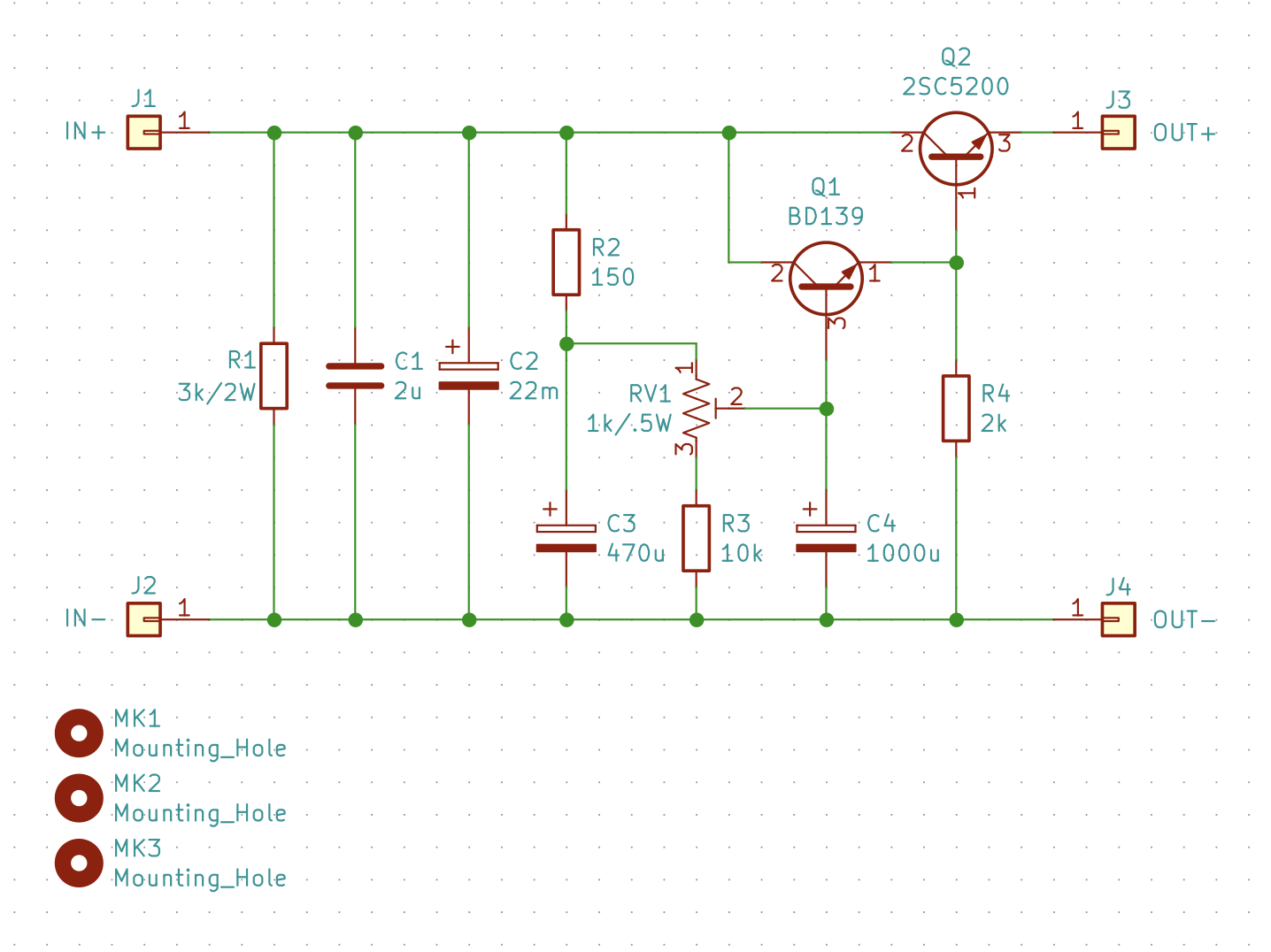
In looking for something with a lower dropout, I started digging into implementing the circuit proposed by Mark Johnson at http://www.diyaudio.com/forums/soli...asy-capacitance-multiplier-4.html#post4858155. I have also taken into consideration AndrewT’s suggestions at http://www.diyaudio.com/forums/soli...asy-capacitance-multiplier-6.html#post4861961, implementing a 1K, single turn trim pot in series to ground with a 10K resistor for R2/R3 as to not exceed the power handling of the trim pot.
Other than that, I increased the C4 to 1000uF since physically, they are similar size-wise and in simulation it shows a drop in Vpp with the increased value. I also added a bleeder resistor and bypass film cap for C1.
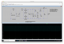
Below are my simulations of the dropout at various resistance ratios for the variable resistor (R6/R3 in the simulation) at about a 2.5A load. This is my first time playing with LTSpice, please let me know if anything seems woefully off!

From this simulation, I got the follow Vrms and Vpp for differing R6/R3 ratios:
inrms: RMS(v(in))=27.1781 FROM 0 TO 1
inpp: PP(v(in))=1.22991 FROM 0 TO 1
with 100/900:
RMS(v(out))=25.4105 FROM 0 TO 1
PP(v(out))=0.00274277 FROM 0 TO 1
with 500/500:
RMS(v(out))=24.3644 FROM 0 TO 1
PP(v(out))=0.00278091 FROM 0 TO 1
with 900/100:
RMS(v(out))=23.342 FROM 0 TO 1
PP(v(out))=0.00276566 FROM 0 TO 1
This shows the dropout voltage changing accordingly, however the Vpp does not seem to differ much. I very well could not be measuring these data points correctly, perhaps Vpp is not the correct measurement for ripple here?
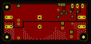
Finally, my implementation is shown below. Let me know if there are any concerns with my schematics, interpretation of Mark’s idea, or flaws in my layout.
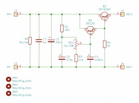
Schematic:
Top Copper:

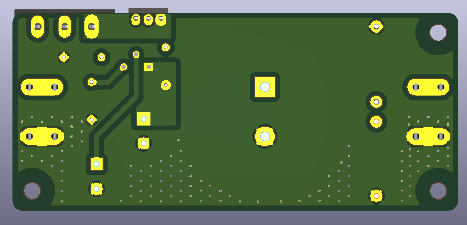
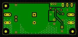
Bottom Copper:

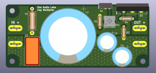
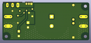
Rendering:

The PCB is 90x40mm with mounting holes at 82x32mm.
DigiKey BOM: Index - My Digi-Key
Thank you all for your review, and Mark Johnson for your circuit. xrk971, let me know if you think this would better sit in its own thread.
I am looking to add a cap multiplier after a SMPS for my Mofo build. Unfortunately, the SMPSes I have will only provide about 26v until going into over voltage and I am looking to run the Mofo at 24v. The 4v dropout of the circuit discussed here will not fit my needs.
In looking for something with a lower dropout, I started digging into implementing the circuit proposed by Mark Johnson at http://www.diyaudio.com/forums/soli...asy-capacitance-multiplier-4.html#post4858155. I have also taken into consideration AndrewT’s suggestions at http://www.diyaudio.com/forums/soli...asy-capacitance-multiplier-6.html#post4861961, implementing a 1K, single turn trim pot in series to ground with a 10K resistor for R2/R3 as to not exceed the power handling of the trim pot.
Other than that, I increased the C4 to 1000uF since physically, they are similar size-wise and in simulation it shows a drop in Vpp with the increased value. I also added a bleeder resistor and bypass film cap for C1.
Below are my simulations of the dropout at various resistance ratios for the variable resistor (R6/R3 in the simulation) at about a 2.5A load. This is my first time playing with LTSpice, please let me know if anything seems woefully off!
From this simulation, I got the follow Vrms and Vpp for differing R6/R3 ratios:
inrms: RMS(v(in))=27.1781 FROM 0 TO 1
inpp: PP(v(in))=1.22991 FROM 0 TO 1
with 100/900:
RMS(v(out))=25.4105 FROM 0 TO 1
PP(v(out))=0.00274277 FROM 0 TO 1
with 500/500:
RMS(v(out))=24.3644 FROM 0 TO 1
PP(v(out))=0.00278091 FROM 0 TO 1
with 900/100:
RMS(v(out))=23.342 FROM 0 TO 1
PP(v(out))=0.00276566 FROM 0 TO 1
This shows the dropout voltage changing accordingly, however the Vpp does not seem to differ much. I very well could not be measuring these data points correctly, perhaps Vpp is not the correct measurement for ripple here?
Finally, my implementation is shown below. Let me know if there are any concerns with my schematics, interpretation of Mark’s idea, or flaws in my layout.
Schematic:
Top Copper:
Bottom Copper:
Rendering:
The PCB is 90x40mm with mounting holes at 82x32mm.
DigiKey BOM: Index - My Digi-Key
Thank you all for your review, and Mark Johnson for your circuit. xrk971, let me know if you think this would better sit in its own thread.
Attachments
Looks nice ! For dual rail would a complementary version with BD140 and 2SA1943 be needed or could one simply use two in series?
Probably a new thread would be best as it’s different. Thanks for bringing to our attention though and let us know how it works.
Probably a new thread would be best as it’s different. Thanks for bringing to our attention though and let us know how it works.
- Home
- Amplifiers
- Power Supplies
- Juma's Easy-Peasy Capacitance Multiplier