Mark,
Yes I believe your drawing is right, please look at the second page of this very nice article Fig.56. There you see what I mean:
https://www.die-wuestens.de/iz/RECT.pdf
Thanks a lot !
Yes I believe your drawing is right, please look at the second page of this very nice article Fig.56. There you see what I mean:
https://www.die-wuestens.de/iz/RECT.pdf
Thanks a lot !
Interesting
Blitz,
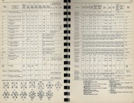
That's interesting. Here is a look at some of the specs for 80 series rectifiers. Check out the voltage drops between the tubes.
Now I know why they were putting mercury in them to keep the voltage drop at 15 Volts versus 60V or 91V for non mercury rectifiers.
Some other tube specs say you can mount the mercury vapor tubes in different ways; e.g., my B&K700 tube tester has it mounted horizontally to keep the case thickness smaller. It is also lined with asbestos cloth to keep it flame retardant.
Blitz pg 75, right column, 1st para. describes Fig 60 as having three rectifiers tubes and delivers three current pulses per cycle.
I wonder how that stacks up against one of them there
high-fa-LOOT-en ZTX/MUR/HEXFRED diode thing-ies?
Cheers,
Cit: General Electric. (date unknown). Tubes, Essential Characteristics: Receiving tubes, Television Picture tubes, Special-purpose tubes. General Electric, Electronic Components Division, Schenectady 5, New York, U.S.A.
Blitz,
That's interesting. Here is a look at some of the specs for 80 series rectifiers. Check out the voltage drops between the tubes.
Now I know why they were putting mercury in them to keep the voltage drop at 15 Volts versus 60V or 91V for non mercury rectifiers.
Some other tube specs say you can mount the mercury vapor tubes in different ways; e.g., my B&K700 tube tester has it mounted horizontally to keep the case thickness smaller. It is also lined with asbestos cloth to keep it flame retardant.
Blitz pg 75, right column, 1st para. describes Fig 60 as having three rectifiers tubes and delivers three current pulses per cycle.
I wonder how that stacks up against one of them there
high-fa-LOOT-en ZTX/MUR/HEXFRED diode thing-ies?
Cheers,
Cit: General Electric. (date unknown). Tubes, Essential Characteristics: Receiving tubes, Television Picture tubes, Special-purpose tubes. General Electric, Electronic Components Division, Schenectady 5, New York, U.S.A.
Attachments
Thanks Rick,
and 120 degree phase difference too.
Question: With UF and Freds etc., wasn't too clear, with each switch on/off being a small step of the 60 Hz AC wave. there would be very very small increments that increase or decrease according to the phase angle as opposed to a rectifier having one long pulse per 360 pulse?
Wondering how many for the Freds. Now that I think about it, it's in their data sheet and is the 1/time, i.e., frequency.
Cheers,
Someone asked by PM what is the aluminium extrusion housing I used in my build in post #952. Thank you for your interest. It is a simple, cheap aluminium extrusion housing I bought years ago from the Electronic Flea Market in Shumsuipo, Hong Kong. Measures 100x 75 x 35mm.
You can get much better quality ones from Fischer, e.g. the FR 80 42 100 ME. FR 80 42, Design cases, Cases f.case, Fischer Elektronik Available from Reichelt, Buerklin, ...., etc.
Blank cases, so you have to do your own cutout.
Cheers, Patrick
You can get much better quality ones from Fischer, e.g. the FR 80 42 100 ME. FR 80 42, Design cases, Cases f.case, Fischer Elektronik Available from Reichelt, Buerklin, ...., etc.
Blank cases, so you have to do your own cutout.
Cheers, Patrick
I just leave my Quasimodos (and Cheapomodos) as bare PCBs with no enclosure at all. Partly that's because my lab bench is an electrical isolator: cheap Ikea melamine laminate. Partly that's because I run my tests using low voltage DC power supplies, so low that they won't cause electric shocks if I touch exposed components.
I tape the Quasimodo/Cheapomodo PCB to the lab bench using blue painter's tape. Then I connect wires to the supply (crocodile clips) and to the transformer (Euroblox screw down terminals), and I tape those wires to the bench too, making the apparatus even more steady. Then I connect my scope probe(s) and ground clip(s) and start measuring.
An advantage of leaving *modo as a bare board with no enclosure, is that it doesn't take up much storage room. I've got four of them in a little plastic food storage tub with a lid, plus an assortment of different values of snubber capacitor and trimmer potentiometer in a tiny ziplock bag.
Another advantage of no enclosure is: it's easy to probe internal nodes if you want to. It's also easy to remove the trimmer, measure its resistance, and reinstall the trimmer onto the board. Without needlessly long wires connecting off-PCB to a front panel mounted pot, wires which add unwanted inductance to the snubbing impedance.
It's a tool to be used, two or three times a year, and then tossed back in the closet to make room on the lab bench for other tools. It's not a sculpture to be revered and admired. Notice the words "test jig" in the title of this thread and on the title page of the Quasimodo design note. They convey the degree of fancy presentation that Quasimodo deserves: none.
If my lab bench were made of conductive metal instead of insulating plastic, I suppose I would probably bolt one of my Quasiomodos onto a block of wood, a block which is thick enough and heavy enough to prevent tipping over: the "small and heavy" design. Another design which prevents tipping over is the "large and light" block of wood, whose dimensions are much bigger than the Quasimodo PCB, say 30 cm by 15 cm. Now the wood block can be only 5mm thick. Center the little 10 by 5 cm PCB on this block and it will never tip over. But it is awfully big and annoying to store.
Last edited:
Thank you Mark, Patrick, Rick, and others for explaining. It is these thoughts that you share that help me keep my thinking on track and focused.
So now I've got all the hard to gather parts to build a proper Quasimodo v4 especially the link and parts from Arrow, which other distributers didn't have. Chalk up one for our side.
Going back through the X-modo threads I've picked up and a few common themes.
Mark doesn't like fooling around with Oxen-Scheisse processes and proceedures.
If it can be done quickly and cheaply (it doesn't mean using inferior parts) saving time he goes for it. He also doesn't baby sit you and expects one to do their share of the fun.
I'm in the process of reconciling the layout on the cheapo-modo vectorboard with the V4 through hole board and their schematics on a vectorboard for me. I just realized (I'm slow) that I should be looking at the Gerber files to see the trace layouts. Now I'm wondering if it would have been better to get a different vectorboard (not the one with the horizontal traces across the length but either the one with three holes per trace of the a pad per hole.
I was going to add to this but I've just had a "mature moment" (I forgot what it was.)
Cheers,
I got my Quasimodo up and running...great machine. While I am still in the learning phase, may I ask how do you measure / optimize the snubbers for each individual leg of a Centre Tapped transformer ?
I have read the manual and when I connect one secondary end to CT as described there, I get a nice clean curve. When I leave it open, So I measure only one leg and leave the second leg unconnected, I get a bit of a different curve with some riplles in it like if you would have when other secondaries on the same transformer are left open. We are here talking about a larger EI transformer with 450-0-450V...so how would you actually measure each leg correctly without the other open leg influencing the measurement ?
I have read the manual and when I connect one secondary end to CT as described there, I get a nice clean curve. When I leave it open, So I measure only one leg and leave the second leg unconnected, I get a bit of a different curve with some riplles in it like if you would have when other secondaries on the same transformer are left open. We are here talking about a larger EI transformer with 450-0-450V...so how would you actually measure each leg correctly without the other open leg influencing the measurement ?
Hi Blitz,
What your scope is probably showing is 'coupled inductance', which isn't what we're trying to minimize.
All other windings must be shorted -- including the other leg of the center tapped one that you're adjusting. That way you'll evaluate the Leakage Inductance, which is the portion that, by definition, is not coupled.
Maybe try as others have suggested here, a known-value coil -- say in the 50 to 100 micro-Henry range. It'll give you a better idea of how the scope trace should look.
Best Regards,
Rick
Okay, now that I have 100 of the NTD4906 chips in stock I have a couple of questions about their use.
In the Quasimodo, we use it to knock on the transformer and get it to "ring".
As with most parts that MJ--the Michael Jordan of Solid State, selects typically best in class at their price point and he's got a keen sense of no B.S. circuits that just plain work. Now, please forgive my ignorance here as I'm a relative solid state newbee. If MJ wants to join in that's fine, but not required....
What are some of the other uses for the NTD4906? I see CPU Power deliver and DC-DC converters....
I probably won't be building these, however surely the have uses for the tinkerer, DIY fix-it and make it better, stronger, faster?
I was looking at the data sheet to see if there was a noise disclosure in the data sheet. Wondering if this could work in lieu of the control FET in this circuit?
Cheers,
Attachments
Last edited:
NTD4906 had the very best Marks Figure Of Merit For a Quasimodo MOSFET, among all thru hole MOSFETs with Logic Level (<= 2.5V) Threshold Voltage, sold and in stock at DigiKey in September 2013.
F.O.M. = 1 / (RdsON * QgTOT)
What else could you use it for? I have no idea. Any general purpose application where a low threshold voltage NMOS would work, and where you know in advance that no heatsink will be required, and where RdsON less than 8 milliohms is beneficial.
F.O.M. = 1 / (RdsON * QgTOT)
What else could you use it for? I have no idea. Any general purpose application where a low threshold voltage NMOS would work, and where you know in advance that no heatsink will be required, and where RdsON less than 8 milliohms is beneficial.
With a logic level <= 2.5 Threshold Voltage (TV), that wouldn't preclude it being used in a standard 5V TTL circuit as it would capture even low pulses from 2.5 to 5V? I'm trying to recall what the Threshold Voltage is in the F-16 aircraft. When I was working the Lockheed Martin Plant in Fort Worth, the electric guys were always B*tching about folks using the standard multimeters changing the aircraft's breaker settings because the check voltages of the meters were too high.
cheers,
cheers,
SyncTronX,
As far as the AGC function in the thumbnail you posted in #1391, the NTD4906 would be a lousy choice. The parasitic 'body' diode would cause problems, as would the abrupt switching nature of the part -- remember, it's capable of 9 milliohms. The circuit's designed-in JFET probably functions over a range of a few tens, to a hundred or two ohms, with a control voltage of minus two or three volts.
Mark has a great point, too -- you have the inventory, if you smoke a few 9-1/2-cent parts gaining some knowledge bits, big deal -- have some fun! The lessons will only stick better . .
Regards,
Rick
Last edited:
EasyEDA.com quotes a price of €21.40 for ten Quasimodo V4 PCBs, shipped to Greece, with a total delay of 7 days.
I learned this by visiting the super handy website pcbshopper.com and telling it I have a PCB whose dimensions are 49mm X 99mm , which is just a little bit larger than the real Quasimodo dimensions. It gives price quotes and delivery estimates for dozens of PCB fabs.
I learned this by visiting the super handy website pcbshopper.com and telling it I have a PCB whose dimensions are 49mm X 99mm , which is just a little bit larger than the real Quasimodo dimensions. It gives price quotes and delivery estimates for dozens of PCB fabs.
- Home
- Amplifiers
- Power Supplies
- Simple, no-math transformer snubber using Quasimodo test-jig