Personally, if extending the height of the panel wasn’t an option to increase area, I would probably halve the values to pick up 3dB maxSPL headroom and still retain more than acceptable polar response. As arend-jan mentioned, it comes down to tradeoffs, and what is important to your listening enjoyment.
This is something that I will definitely experiment with. I am using SMD resistors and I have enough space to double them up (in parallel) and halve all of the resistances. I will probably try both. I have plotted out the speaker locations in my room as well as my seating position and I think that the polar response of the latest simulation is more than enough. I think that using less resistance may actually be better. Halving the resistance seems to have a reasonable enough dispersion and I would gain some SPL and maybe some imaging.
The only tradeoff is FR at my less-than-ideal seating positions. It's a small sacrifice though. With my 120" screen so close (about 11 feet) the viewing sweet spot is also rather narrow.
Hi Calvin
I'm sorry - perhaps I was being a bit short. I obviously failed to convey my thoughts (late at night). I was not suggesting that ESL-63 is SOTA. I was suggesting that the different types of ESL are sufficiently different that you cannot extrapolate techniques developed empirically for one type of ESL to another. The transformer issue you raise is a good case in point.
The single segment ESL has almost pure capacitance in upper audio band - say 1 nF. If you want wide bandwidth with you must use a transformer with low leakage inductance, and if you want to eliminate influence of amplifier inductance (up to 10 uH say) , you must have relatively low turns ratio, about 50ish perhaps a bit more. As you have discovered, moderately large toroids (50VA, larger if they are stacked to get input voltage rating) work really well. (Plitron transformer C= 700 pF, L=15 mH, N=50)
The ESL-63 and descendants is closer to pure resistor in upper audio band. In that case maximum bandwidth is achieved with transformer with low C. The Quad circuit (two transformers) has L= 3 H, C = 15 pF, N=300 complete opposite of your experience.
The RC transmission line ESL is midway between these two cases. The RC transmission line has an impedance midway between pure R and pure C, and a much easier load to drive than pure C. At 20 kHz the ESL load is equivalent to is about 60 pF//150 k (the characteristic impedance of the transmission line at those frequencies). Maximum bandwidth is achieved with a transformer with 200-400 mH, C = 50-100 pF, and it will comfortably cope with N up to 150 before amplifier output inductances become a problem.
Re segment sizes etc. The low cutoff frequency of the symmetric RC transmission line is 2/(pi.R.C.N^2) where C is segment capacitance, and R is resistance between segments. A good value for full range ESL is a little greater than 100 Hz, and use the diaphragm resonance to fill out the bottom end. Notice that if the segment sizes change, that the total resistance NR and the total capacitance NC, and stay the same for the same cutoff frequency. For N=21, C = 40 pF, R=270 k, the cutoff frequency is 134Hz a good value for full range ESL.
As Bolserst has pointed out, the ESL will need to be a bit higher than at present to give that equalisation at normal listening distances. But having proved the design, another pair of panels will fix that problem")
regards
Rod
I'm sorry - perhaps I was being a bit short. I obviously failed to convey my thoughts (late at night). I was not suggesting that ESL-63 is SOTA. I was suggesting that the different types of ESL are sufficiently different that you cannot extrapolate techniques developed empirically for one type of ESL to another. The transformer issue you raise is a good case in point.
The single segment ESL has almost pure capacitance in upper audio band - say 1 nF. If you want wide bandwidth with you must use a transformer with low leakage inductance, and if you want to eliminate influence of amplifier inductance (up to 10 uH say) , you must have relatively low turns ratio, about 50ish perhaps a bit more. As you have discovered, moderately large toroids (50VA, larger if they are stacked to get input voltage rating) work really well. (Plitron transformer C= 700 pF, L=15 mH, N=50)
The ESL-63 and descendants is closer to pure resistor in upper audio band. In that case maximum bandwidth is achieved with transformer with low C. The Quad circuit (two transformers) has L= 3 H, C = 15 pF, N=300 complete opposite of your experience.
The RC transmission line ESL is midway between these two cases. The RC transmission line has an impedance midway between pure R and pure C, and a much easier load to drive than pure C. At 20 kHz the ESL load is equivalent to is about 60 pF//150 k (the characteristic impedance of the transmission line at those frequencies). Maximum bandwidth is achieved with a transformer with 200-400 mH, C = 50-100 pF, and it will comfortably cope with N up to 150 before amplifier output inductances become a problem.
Re segment sizes etc. The low cutoff frequency of the symmetric RC transmission line is 2/(pi.R.C.N^2) where C is segment capacitance, and R is resistance between segments. A good value for full range ESL is a little greater than 100 Hz, and use the diaphragm resonance to fill out the bottom end. Notice that if the segment sizes change, that the total resistance NR and the total capacitance NC, and stay the same for the same cutoff frequency. For N=21, C = 40 pF, R=270 k, the cutoff frequency is 134Hz a good value for full range ESL.
As Bolserst has pointed out, the ESL will need to be a bit higher than at present to give that equalisation at normal listening distances. But having proved the design, another pair of panels will fix that problem
regards
Rod
So I assembled the a single panel (with a diaphragm) a short while ago and I had some issues. I was getting a periodic clicking sound -> arcing from the bias to a stator. Anyways, it seemed to be only on one stator (I disconnected them to test). Not only was it arcing but it was pulling the coating off! The surface looks chipped in those areas.
I know that Jer had mentioned this happening with the coating not fully dry yet. I'm pretty sure that mine has been dry for about 4 days. Anyways, I disassembled them and I'm going to patch those areas with acrylic nail polish and then re-coat with clear spray acrylic. Then I'm on vacation for a while so it should have plenty of time to dry.
Anyone have any other suggestions or thoughts?
So I assembled the a single panel (with a diaphragm) a short while ago and I had some issues.
The Licron coating should be sufficiently dry in a few hours at room temperature, so that's not the issue. You did apply the Licron AFTER tensioning the diaphragm, right?
Last edited:
Is it a PET film or something else? Did you clean the film with alcohol or acetone before coating?
It is 6um mylar. Actually I just cleaned it gently with compressed air. Perhaps this was not sufficient. I got nervous touching it after tensioning. It seems like it is ready to burst at any second!
Charlie, I did apply the licron after tensioning, after the diaphragm was applied to a single stator. and my worry was not about the drying of the licron, but the curing of the stator coatings.
Hi,
with two- or three-layer coatings of the stators this may occur.
When my panels just have been powder coated but not had their final wet top coating sometimes the effect occurs when arc testing.
The layers are a black colorizing top coat over a white functional base coating.
If the powder has not melted completely pin holes may develop.
When I test the panels I lay down a piece of aluminum foil on the panel and use a higher bias voltage than used later under normal working conditions, together with a rather low valued current limiting resistor of the bias supply.
In case of a pinhole or a defect the black top coating is literally blasted away at the arcing point.
Also the quite strong arc kind of hammers a small spot into the aluminum foil, thereby making identification of the position of the arc easy.
Panels arcing under this test will be rejected and only those passing the test will receive the final wet coating layers and undergo another arcing test.
So, I´m afraid that Your stators are still not insulated well enough.
jauu
Calvin
I agree that the insulation is insufficient. It seems to be the only reason that this would happen. What surprises me is that I did not find any problems while arc testing the panels. I did not, however, use Al foil as you suggested. I simply used some frayed wire acting like a brush.
Also, this only occurred on one of the stators, and mostly on one particular side of the slot edges. Perhaps that stator/edge missed a coating or was insufficiently coated vs the other.
Anyways, I will be patching those problem areas and re-coating tonight. I may even add a few extra coats. Fortunately it was quite easy to disassemble them. I don't mind doing it, but I'd rather not do it too many times (wasting materials and my patience...). I will post some pics later.
Here is a pic of a spot where the arcing occurred and the coating was pulled off.
So I think that the problem is that the coating was not fully cured. The paint oem recommends 5-7 days at 70 Deg F, which I'm pretty sure I did not get. I did the thumbnail test on that panel and it wasn't fully hardened. Most of the time these were sitting in my garage (~50 Deg F) where they will cure slow. I placed them in my basement near a furnace vent for 2 days to speed it up but 2 of the panels did not have an unobstructed line of sight to the vent.
Anyways, I'm going on vacation so I'll finish patching that panel tonight and let these rest for about 10 days. Hopefully that does it!
Attachments
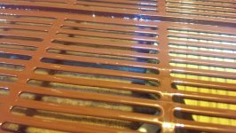
Perhaps it's not clear in the picture: the damaged area is in the center of the picture, on the edge of a slot, it looks grey
There is another grey spot on the right side of the picture on the top surface. This is not a damaged spot, though it looks similar. It is some dirt or debris.
There is another grey spot on the right side of the picture on the top surface. This is not a damaged spot, though it looks similar. It is some dirt or debris.
Here is a pic of a spot where the arcing occurred and the coating was pulled off.
Thanks for the pic.
Based on your description, perhaps it wasn't that the coating was sufficiently thick but that the coating was still conductive since it hadn't fully cured.
So I assembled the a single panel (with a diaphragm) a short while ago and I had some issues. I was getting a periodic clicking sound -> arcing from the bias to a stator.
Often a periodic arcing from diaphragm to stator out in the middle of the panel indicates the bias voltage is set to high for the diaphragm tension used. Basically as the charge builds up on the diaphragm it starts getting pulled off center towards one stator or the other. The more charge buildup, the more force pulling it off center. The diaphragm may even collapse completely to one side and stick to the stator until you turn off the bias supply. If arcing occurs before the diaphragm fully collapses, as in your case, the diaphragm is discharged and it snaps back to the center of the airgap and the cycle starts again.
What method did you use to tension your diaphragm?
What Voltage level were you using for your bias?
With line-powered HV supplies like yours, I find it helpful to use a VARIAC ramp up the bias supply voltage slowly to determine the instability threshold.
Hi , in the picture of ur voltage multiplier you end up with a positive charge on ur menbrame, ive been told you want it to be negative. something with coroding the coating. im not sure this is true. but maybe someone can shine a light on that ?
further looking nice, kind of big openes i think , wich could harm efficiency a bit >?
further looking nice, kind of big openes i think , wich could harm efficiency a bit >?
Hi , in the picture of ur voltage multiplier you end up with a positive charge on ur menbrame, ive been told you want it to be negative. something with coroding the coating. im not sure this is true. but maybe someone can shine a light on that ?
further looking nice, kind of big openes i think , wich could harm efficiency a bit >?
I've heard that too (although I forgot where or when) and I've also heard that positive bias attracts more dust to the diaphragm but I've not experienced any problems with positive bias since rebuilding my panels in 2010.
What I would do differently next time has to do with the charge ring. Next time I would buy copper foil with the conductive adhesive and place the adhesive side (as opposed to the bare copper) against the diaphragm coating for more intimate contact less prone to arcing. Even so, I haven't had any problems using positive bias.
If you want to reverse the bias to negative, you can do so by reversing the diodes' orientations; in which case you would also want to reverse the stator connections to restore phasing between the panel and woofer.
Ah negative bias attracts more dust than positive. That's one that can go on the Electrostatic Loudspeaker Mythbuster todo list, as it is much repeated but has anyone ever verified it?
I did a little research about the charge on common air born pollutants. It appears that dust is for a large part human skin, which charges positively (triboelectric scale). So does human hair. Cigarette smoke also has a positive charge according to companies that make electric smoke filters. And negative ionizers are used as air cleaners, which leads me to believe most air born particles in domestic environments have positive charge.
I have seen quite a few Quad speakers on the inside, some of them probably not been opened for 20, 30 or 40 years even. You can imagine what that looks like.. some of them had at least half a centimeter of dust inside them (like a carpet). But most are just dirty nothing spectacular.
Anyway, Quad electrostatics have dust covers to prevent the dirt from entering the panel. But those can brake. And what I have seen is that the dirt mostly collects on the outside of the panel on the electrodes, not so much on the inside. It does go on the inside but not as much as one would expect.
Quads have positive charged membranes.
A charged electrostatic panel as a whole is neutral charge. The diaphragm has equal but opposite charge to the electrodes. In practice there will be some electric field leaking from the stator holes but the strongest field is on the inside. Now air circulating through the panel will, depending on the polarity, deposit charged particles just as easily to the diaphragm as to the electrodes. I think it would depend on the construction of the panel where (possibly conductive) dirt will do the most damage.
How about the following experiment: two identical metal plates parallel and in proximity of each other on insulated stands, charged with opposite polarities. Just leave it standing somewhere in a corner for a year or so and report back
I did a little research about the charge on common air born pollutants. It appears that dust is for a large part human skin, which charges positively (triboelectric scale). So does human hair. Cigarette smoke also has a positive charge according to companies that make electric smoke filters. And negative ionizers are used as air cleaners, which leads me to believe most air born particles in domestic environments have positive charge.
I have seen quite a few Quad speakers on the inside, some of them probably not been opened for 20, 30 or 40 years even. You can imagine what that looks like.. some of them had at least half a centimeter of dust inside them (like a carpet
). But most are just dirty nothing spectacular.Anyway, Quad electrostatics have dust covers to prevent the dirt from entering the panel. But those can brake. And what I have seen is that the dirt mostly collects on the outside of the panel on the electrodes, not so much on the inside. It does go on the inside but not as much as one would expect.
Quads have positive charged membranes.
A charged electrostatic panel as a whole is neutral charge. The diaphragm has equal but opposite charge to the electrodes. In practice there will be some electric field leaking from the stator holes but the strongest field is on the inside. Now air circulating through the panel will, depending on the polarity, deposit charged particles just as easily to the diaphragm as to the electrodes. I think it would depend on the construction of the panel where (possibly conductive) dirt will do the most damage.
How about the following experiment: two identical metal plates parallel and in proximity of each other on insulated stands, charged with opposite polarities. Just leave it standing somewhere in a corner for a year or so and report back
Ah negative bias attracts more dust than positive. That's one that can go on the Electrostatic Loudspeaker Mythbuster todo list, as it is much repeated but has anyone ever verified it?
I did a little research about the charge on common air born pollutants. It appears that dust is for a large part human skin, which charges positively (triboelectric scale). So does human hair. Cigarette smoke also has a positive charge according to companies that make electric smoke filters. And negative ionizers are used as air cleaners, which leads me to believe most air born particles in domestic environments have positive charge.
I have seen quite a few Quad speakers on the inside, some of them probably not been opened for 20, 30 or 40 years even. You can imagine what that looks like.. some of them had at least half a centimeter of dust inside them (like a carpet
Anyway, Quad electrostatics have dust covers to prevent the dirt from entering the panel. But those can brake. And what I have seen is that the dirt mostly collects on the outside of the panel on the electrodes, not so much on the inside. It does go on the inside but not as much as one would expect.
Quads have positive charged membranes.
A charged electrostatic panel as a whole is neutral charge. The diaphragm has equal but opposite charge to the electrodes. In practice there will be some electric field leaking from the stator holes but the strongest field is on the inside. Now air circulating through the panel will, depending on the polarity, deposit charged particles just as easily to the diaphragm as to the electrodes. I think it would depend on the construction of the panel where (possibly conductive) dirt will do the most damage.
How about the following experiment: two identical metal plates parallel and in proximity of each other on insulated stands, charged with opposite polarities. Just leave it standing somewhere in a corner for a year or so and report back
haha
a year I recond the story came form the book by fikier, about esl's. weird enough most solosounds ESL's are positive charge, only a later cascade i found had negetave charge. wich i found out after fidling around because somehow my left esl was out of phase with the other one, something i blamed the trannie connection layout for (because they where from diferent revision), after changing to another trannie i took a look at the diodes
and ofc they where otherway around.this might be a custom thing from the previous owner though, because on the PCB it states + at the high voltage.
i somehome never had dust problems either with + charge or - charge. at least not so severe that stuf arced, usually when they did arc it whas just the coating on the panel giving up after 30 years of duty. just gently clean them with low pressure airor a dust cleaner with plastic hose worked for me
Both your bias voltage level and diaphragm tension are reasonable for the dimensions of your gap and unsupported width.I tensioned using tape all around the edges of the mylar. I made markings with a sharpie 6 inches apart and stretched until I got about 1.5% elongation in all directions. My bias voltage is about 2700 at the moment.
There was a previous thread on bias voltage polarity which may be of interest.Hi , in the picture of ur voltage multiplier you end up with a positive charge on ur menbrame, ive been told you want it to be negative. something with coroding the coating. im not sure this is true. but maybe someone can shine a light on that ?
http://www.diyaudio.com/forums/planars-exotics/146008-esl-bias-supply-polarity.html
You are right that for a given %open area and D/S spacing, the larger the openings the lower the efficiency. You can actually get a good estimate of the efficiency loss by measuring the capacitance from stator to stator and comparing with calculation for a solid flat plate capacitor of the same overall dimensions and gap.kind of big openes i think , wich could harm efficiency a bit >?
C = ε0 x A / d
where
C = capacitance, in pF;
A = area of plates, in cm^2;
ε0 = electric constant (ε0 ≈ 0.08854 pF/cm)
d = separation between the plates, in cm;
These stators have roughly 50% open area, slot widths of 1/8", and D/S spacing of 1/16".
Surprisingly, based on my experiments, even with this large slot width and small air gap the measured capacitance will be down only about 20% from the solid flat plate. This would indicate a loss of about -2dB relative to what would be possible with lower % open area and/or small slot openings.
In general if your D/S spacing is at least as large as your stator openings, losses will be < -1dB.
- Status
- This old topic is closed. If you want to reopen this topic, contact a moderator using the "Report Post" button.
- Home
- Loudspeakers
- Planars & Exotics
- First time ESL builder