Thx bolsert ! SO this is why audioststic had suck large openes ? Because they 3 mm D/S spacing
Last edited:
Thx bolsert ! SO this is why audioststic had suck large openes ? Because they 3 mm D/S spacing
I would guess that the reason Audiostatic used large spacing between their wires was to simplify construction and minimise cost...and perhaps improve "see thru" optics.
The reason they can use the large spacing they do (without losing more sensitivity than common sense might suggest) is because, as you stated, the D/S spacing they use is large as well.
Last edited:
So I am getting closer to having fully hardened (or at least close) panels. Some testing showed that the panels were definitely not fully cured when they were first tested with HV. Anyways, I have a fan constantly blowing on them and it seems to have sped up process quite a bit. It seems that my garage has terrible air circulation which slowed the curing process to a halt.
Hopefully this weekend I'll be ready for some more testing.
Hopefully this weekend I'll be ready for some more testing.
So I haven't been on here for a while. I ended up altering my machining and coating sequence and then made a small panel (about 4x12 inches) to test. It worked great so I went ahead and machined new 11x35 inch stators.
I have one speaker panel fully finished and it has tested very well. I was able to max out my spare small amp with no issues. Next I'll put it through its paces with a big boy amp (QSC RMX 2450). If it fares like the smaller panel I'll be good to go for finishing the other panel and building cabinets.
I'll post some more info in the next few weeks.
Attachments
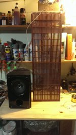
I am using it from 200 or 250 Hz and up.
I have driven it lower but not with much power. I will try to do that with the bigger amp.
After it had some time for the diaphragm to charge I was able to drive them very loud. I was still limited though as I don't have a proper woofer to handle the low end.
I have yet to make some good FR measurements but just using some crude SPL measurements it seems that the panel is performing on-par with its simulated expectations (I used resistor values from Post 88).
EDIT: I am using a bit of a different segmentation than post 88. I have 33 total segments, with 20k before the first and 220k between each one after. The off-axis response is ridiculous. It's better than just about any speaker that I've heard.
Last edited:
If you are using the typical Toroidal Power Transformer setup you won't be able to get much lower than 300Hz with a large amplifier due to core saturation.
Unless you are using 4 cores or more and LV windings higher than 6V.
FWIW
jer 🙂
Unless you are using 4 cores or more and LV windings higher than 6V.
FWIW
jer 🙂
If you have all of the 6v winding's in parallel then it is the same 300Hz fo about 40Vrms.
But if you have them in a series Parallel as set for 12v then theoretically you will be able to get as low as 150Hz.
But this also cuts your ratio in half so this cuts your drive voltage in half as well, your efficiency is dropped by 6db and you have to drive your bigger amp twice as hard to get the same SPL.
so your only gain is going to be able to get lower with them, with a loss of efficiency.
There are many ways to configure the setup to help keep the impedance on the low end to get to low as well while increasing the ratio a bit too.
I will have more on this in a few months when I have same Antek cores to work with, When I get back from picking up Maveric's ESL's in Georgia.
http://www.diyaudio.com/forums/planars-exotics/165495-start-finish-esl-hybrid.html#post2168352
I will do a full test on that setup to post to show what can be expected to the newcomers of this Fabulous hobby !! 😉
Then I can show some tweaks that you can do to get a little more out of them with out having to use more than 2 or 4 cores.
I will try every possible configuration and the show the impedance graphs of the transformers as I have done in the past as I was using another manufactures 200watt transformers that I have and not the Antek's.
I only have a 100watt version of one of Antek that was sent to me for testing.
So, it will be some interesting data to compare too, once I get them and back up here in Michigan and back into testing again.
jer 🙂
Last edited:
For the segmented ESLs, such as jamesthomas128 has built, a stack of small toroids is best, and cheapest.
For a single segment ESL (pure capacitive load) you need transformers with a low leakage inductance as jer recommends, which comes with larger transformers. Commercial ESL transformers are designed for this case too.
For the segmented ESL (RC transmission line), which has an equal mixed resistive and capacitive load, the optimum transformer has middle range values for both leakage inductance and winding capacitance and large toroids are not ideal (C too high). A a stack of small (15VA) toroids is very good. DO NOT buy commercial ESL transformers for a segmented design.
For example, 4 off 9V:230V (50Hz) transformers with the 9V windings in parallel and 230V windings in series will give a 200/50 x 9V =36Vrms input voltage capability at 200 Hz, and a 230/9*4=1:102 step-up ratio. Do not buy transformers with the dual 115V winding, the capacitance is very high.
For purely resistive load (ESL 63 - LC transmission line ESLs) you want the smallest winding capacitance you can get, hence large winding inductance, toroids are hopeless. Commercial ESL transformers are worse than hopeless.
best wishes of the season everyone. Those of us in the southern hemisphere will be busy with DIY projects for a couple of weeks!
Rod
This raises a good question. I have enough anteks to get a 150:1 step up. I also have enough 230/6 VTX toroids to get the same step up. I intend to try both and compare results. I wonder if I will ever notice a difference at reasonable power levels and above 200-300 HZ....
With that many different cores to work with it would be worth your while to read through this thread,
http://www.diyaudio.com/forums/planars-exotics/161485-step-up-transformer-design.html#post2088330
It is 6 pages long but it is a wealth of information on step up transformer design.
I started off with a common bargain deal transformer that I had mentioned and learned how to do the certain tests I needed, with the help of all of the DIYer's here in these threads, on how to find the unknown parameters of the transformers that I am using.
I must admit that it was when I read in some thread that Calvin wrote, and CharlieM's build, about using the Toroid's that finally got me back into this hobby in 2009.
I had finally built my First ESL's back in 2003 after some 15 years of prior research on the subject inspired by Roger Sanders original Audio Amateur article.
Not having a proper transformer was the one thing that had set me back for the last 6 years prior to 2009 by using Tube OPT's that kept failing until I had no more that worked.
Anyhow,
I learned how to find Parameters such as Leakage Inductance, Stray Self Capacitance and how these effect the transformers performance and bandwidth.
There are several other very good discussions about this that had branched off of that thread as well during that time in various spots.
The bottom line is that it eventually lead me to what I was really trying to find out, learning how to plot the actual impedance curve of the transformer itself, and also, with and with out the ESL load connected to it as well.
I found out how easily this can be done now with the very same software and test jig it takes to plot the impedance of any dynamic driver using programs such as REW, Visual Analyzer, AcustikA's SimpleS and even HOLMImpluse could be used as well.
By just by using a few resistors, a unity gain opamp buffer and a sound card!
It opened up a whole new world of understanding how the transformer works for me.
There is a lot more to it then just its voltage and winding ratios.
I had to learn the hard way myself and that is why I had jumped in to that thread.
Although, I didn't mean to hijack the thread and take it over, But the info is all good and it set the grounds for a better understanding of the step up transformers rather than them being some kind of mystery device that just worked.
It was one of those things that was done out of necessity for the average DIYer (like myself) who could not afford those fancy Plitron Step-up Transformers who's ridiculous prices per unit was then starting to skyrocket towards $400 to $500 a piece!!!
I had started a tutorial on what I had learned over at ESLDIY but I never got around to finishing it.
So once I get everything back together I will start a new thread and finish what I had promised everyone that I would do.
Explain it in fully understandable detail!!!
All of the text that I have done at ESLDIY is still there but the pictures are gone and I am not too happy about that right now.
It will be some time before I will be able to get together all of the info again and straighten it out.
Meanwhile all of it can be found in these threads as well starting with the above link.
Here is the link the links on the impedance measurement techniques as well as a nice little buffer that I designed that I plan on using drive the transformers primary with instead of using one of my big macho power amps.
http://www.diyaudio.com/forums/soft...re-capacitor-impedance-graph.html#post3816243
And,
http://www.diyaudio.com/forums/software-tools/212908-exploring-visual-analyser-va-3.html#post3383659
If you are interested in seeing the Transformer Test Jig schematic's let me know and I will post it for you as it is now gone from ESLDIY.
I am not even sure if the the link in that post to the site even still works either, as all of that stuff has been changed since then.
I love your build!!
I am very grateful to hear your report on the High frequency dispersion issue using the electrical segmentation method and how well it works!!!
I agree with most everything that Golfnut was saying, but anytime you can get a lower amount of leakage inductance and a lesser amount of stray capacitance this is only a good thing. 😉
Connecting the two 120v winding in series is the biggest down fall of the extra capacitance.
It doubles it as measured!!
I am not sure if the 230V transformers are actually any better as I have not had one to test.
It depends greatly on how the winding was wound.
But I can say that my 200watt cores have about 1/3 to 1/4 of the capacitance than what was stated for the 50 watt Antek's and probably at least 1/2 to 1/3 that of the 100watt model that I do have.
They also have 2x120v windings as well.
I forget the exact numbers but I will have more on this when I get back home from my trip to the south in a few months.
I will explore this in more detail when the time comes but there are ways to improve this with what you are using.
I have done this with the cores that I do have but this means a not being able to go very low as easily as well.
But it is a good compromise of a higher ratio and utilizing a higher crossover frequency.
You may understand this once you start reading the First thread that I had posted.
What it does mean is a better operating efficiency for their operating range and a higher (safer) impedance for the amplifier to drive as well.
You will find that finding a woofer system that can keep up will be your biggest hurdle, now that you have made a system that exhibits a decent amount of efficiency and SPL.
Especially now that the dispersion issue has been solved !!! 🙂
Cheers!!!
jer 🙂
Hi,
routing the copper costs on drill tools and generates sharp edges.
It´d be preferrable to etch slightly larger areas than You will drill or route afterwards, so that a copper free rim develops around the holes.
The copper side may then be sealed with laquer, for example a high viscosity PCB sealant (see Peters.de, Elpeguard DSL1600 series et al).
High viscosity laquer to achieve a nice rounding of the hole edges and a thick build-up.
jauu
Calvin
Actually I got a nearly perfect edge by machining the copper. The key was to use the proper tools and feed rates (I will post some pics of freshly machined stators). I have the copper machined back away from the slot edges by 1/32 inch. So I then coated the copper side with flat red primer (thick enough to round off all edges). I then added a few coats of matte clear Rustoleum 2x.
Using the big amp (rated at about 1200 watts into 2 ohms) I was able to drive my small test panel (unsegmented) to max amplification with no distortion or issues above 450 HZ. I'm getting similar results with these large segmented panels but down to 250-300hz.
Btw, all of these tests so far have been made with dual 230/6 VTX toroids.
Hi,
routing the copper costs on drill tools and generates sharp edges.
It´d be preferrable to etch slightly larger areas than You will drill or route afterwards, so that a copper free rim develops around the holes.
The copper side may then be sealed with laquer, for example a high viscosity PCB sealant (see Peters.de, Elpeguard DSL1600 series et al).
High viscosity laquer to achieve a nice rounding of the hole edges and a thick build-up.
jauu
Calvin
Excellent !!!!! 🙂
I had drove my little panel at full power with my Crown DC300a and I had no distortion!!
Except when the ESL exploded and caught Fire!! He,he,he,he
jer 🙂
I had drove my little panel at full power with my Crown DC300a and I had no distortion!!
Except when the ESL exploded and caught Fire!! He,he,he,he
jer 🙂
Last edited:
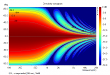
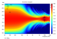
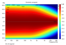
… The off-axis response is ridiculous. It's better than just about any speaker that I've heard.
Indeed, symmetrically segmented flat ESLs can produce dispersion patterns that best most any other ESL(or dynamic loudspeaker for that matter) in broad uniform coverage, and directivity that trends smoothly with frequency. It has been fun exposing people only familiar with flat un-segmented panels(attachment #1), 30 deg arc curved panels(attachment #2), to the smooth/broad coverage of properly segmented flat ESLs(attachment #3). Often they simply don’t believe what they are hearing based on the big flat panels their eyes are seeing. They have to get out of the listening chair and walk up to the panels to check things out, and then wander back and forth across the listening area.
Attachments

As promised, pics of a freshly machined stator. They are practically ready to coat immediately after machining.
After machining I removed a few burrs (each stator had a few) and then cleaned them up further with steel wool. After that I cleaned them with compressed air and started coating.
With Jer's advice and my own experience (painstaking, unfortunately) I coated each stator heavily with Rustoleum Flat Red primer. I then added acrylic ribs for strength with epoxy. Then I added some a few more coats of primer. Finally I topped it off with a few coats of Rustoleum 2x Matte Clear.
Attachments
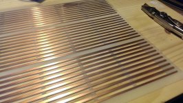
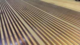
BTW, experience really payed off when machining these stators. Previous attempts required much deburring and sanding, etc. These panels required almost no prep work for coating.
The key was to use a Diamond-cut bit for the slots and a PCD coated end mill for removing the Cu. Also, to keep Cu burrs to a minimum, and to keep the slots clean (Garolite has a tendency to fray) and smooth I machined this with a very high feed rate, much higher than I was originally comfortable with.
The key was to use a Diamond-cut bit for the slots and a PCD coated end mill for removing the Cu. Also, to keep Cu burrs to a minimum, and to keep the slots clean (Garolite has a tendency to fray) and smooth I machined this with a very high feed rate, much higher than I was originally comfortable with.
- Status
- Not open for further replies.
- Home
- Loudspeakers
- Planars & Exotics
- First time ESL builder