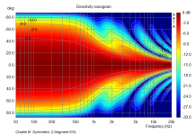
Indeed, symmetrically segmented flat ESLs can produce dispersion patterns that best most any other ESL(or dynamic loudspeaker for that matter) in broad uniform coverage, and directivity that trends smoothly with frequency. It has been fun exposing people only familiar with flat un-segmented panels(attachment #1), 30 deg arc curved panels(attachment #2), to the smooth/broad coverage of properly segmented flat ESLs(attachment #3). Often they simply don’t believe what they are hearing based on the big flat panels their eyes are seeing. They have to get out of the listening chair and walk up to the panels to check things out, and then wander back and forth across the listening area.
You guys are killing me... that dispersion graph was the last straw. Now you've given me the itch to build some segmented panels... I can't afford this hobby!
 :hypno2
If I decide to pull the trigger, I will start another thread to pick your brains-- electronics dummy that am, I might need some help modeling the segments and resistor ladders. And I got this crazy idea to make the dispersion pattern switch selectable (narrow for solo listening or wider when entertaining guest). Has anyone done this?
Last edited:
Good Show Charlie!!!!!
Can't wait to see your Next Build !!! 😉
May I suggest my Painted TIG Rod method?
It is very easy to do and not as costly, the only drawback is TIG is only availble in 36" lengths but that shouldn't be an issue if you need it to be longer.
Just use the download and install the segmented ESl simulator and get playing with that for your next design here,
http://www.diyaudio.com/forums/plan...tor-esl-simulator-esl_seg_ui.html#post3192348
jer 🙂
Last edited:
If I decide to pull the trigger, I will start another thread to pick your brains-- electronics dummy that am, I might need some help modeling the segments and resistor ladders. And I got this crazy idea to make the dispersion pattern switch selectable (narrow for solo listening or wider when entertaining guest). Has anyone done this?
This would be difficult and interesting because all of the switching would be on the high voltage side (although voltage between adjacent segments won't be as high). Quite frankly I love the idea though.
" And I got this crazy idea to make the dispersion pattern switch selectable (narrow for solo listening or wider when entertaining guest). Has anyone done this? "
Certainly an interesting technical challenge, but actually solo listening is better with the wider dispersion too, ambient reflections more balanced, and you don't have to hold your head in a vice.
From a technical perspective
> you would have to switch all resistors in the RC transmission line
> it would change the low cut-off frequency of the ESL, and would require an accompanying change in the damping of the diaphragm resonance to maintain a flat bottom end.
> but you would pick up a couple of dB in sensitivity.
regards
Rod
Hi,
I see this idea floating from time to time in this forum.
It would be possible to use high voltage reed relays(It's possible to find such ones in ebay) to short out and bypass segmentation resistors. Then of course frequency response must be corrected as mentioned in previous post. However the price of such relays is substantial. It might even be cheaper to buy good electrostatic or dynamic headphones for solo listening
Regards,
Lukas
Last edited:
However the price of such relays is substantial. It might even be cheaper to buy good electrostatic or dynamic headphones for solo listening
^^^^^This
You guys are killing me... that dispersion graph was the last straw. Now you've given me the itch to build some segmented panels... I can't afford this hobby!... And I got this crazy idea to make the dispersion pattern switch selectable (narrow for solo listening or wider when entertaining guest). Has anyone done this?
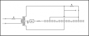
One option to "baby step" your way into segmented ESLs would be to modify your existing ESL by separating the rear stator into 3 separate electrical sections along the existing vertical foam tape dividers. Leave the front stator all one piece for holding the diaphragm tension.
This would minimize cost and let you use construction techniques you are comfortable with.
With the 3 stator sections you could create a symmetric 2 segment ESL as shown in the schematic.
The center segment would be driven straight from the transformer, and the outer two section connected together to form the second segment and driven thru a resistor.
You could easily revert to un-segmented if you bypassed the single segmentation resistor with a jumper.
The polar response will provide a wider sweet spot than you currently have and a much improved high-frequency balance to the sound when outside the sweet spot.
Attachments
One option to "baby step" your way into segmented ESLs would be to modify your existing ESL by separating the rear stator into 3 separate electrical sections along the existing vertical foam tape dividers. Leave the front stator all one piece for holding the diaphragm tension.
This would minimize cost and let you use construction techniques you are comfortable with.
With the 3 stator sections you could create a symmetric 2 segment ESL as shown in the schematic.
The center segment would be driven straight from the transformer, and the outer two section connected together to form the second segment and driven thru a resistor.
You could easily revert to un-segmented if you bypassed the single segmentation resistor with a jumper.
The polar response will provide a wider sweet spot than you currently have and a much improved high-frequency balance to the sound when outside the sweet spot.
WOW!!! I had not imagined it possible to segment a perf metal panel leaving one stator intact.
Actually, I'm intrigued by the thought of building segmented wire stators using .035 dia copper coated TIG rods glued to black plastic egg crate light diffusers and coated with clear polyurethane. These could replace the 1'x4' perf metal panels in my existing hybrid TL speakers.
My problem is that I don't yet grasp how the resistor ladders work or what widths are required to segment the wire groups to get balanced response.
I left my laptop at my GF's house last weekend (using my Ipad now) so I haven't yet downloaded the calculator, let alone figured it out. I will have my laptop back this weekend.
I'm pretty good with woodwork and mechanical stuff but I'm a total dummy with computer programs, math and electronics.
Rather than continuing to hijack James' thread to ask my questions, I'm starting a new thread HERE.
Last edited:
So while coating my second panel I have been testing the first one with different transformer configurations (VTX and Anteks, various step-up ratios).
It seems that the best results so far are using 4x VTX 230/6 or 4x Antek 115/6 for a total step-up ratio of 1:150. My small amp delivers up to 30Vrms and with that I had no issues beyond amp clipping.
It seems that the best results so far are using 4x VTX 230/6 or 4x Antek 115/6 for a total step-up ratio of 1:150. My small amp delivers up to 30Vrms and with that I had no issues beyond amp clipping.
Attachments
![IMAG0803[1].jpg](/community/data/attachments/411/411793-4a85c9e578b501c27a61f8c22b91ee32.jpg?hash=SoXJ5Xi1Ac)
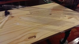
Just finished adding acrylic ribs/stiffeners to the stators for my 2nd panel. A few more coats of red primer and then matte clear will finish them.
Hi,
I suggest to test insulating capabilities of your coating layer before gluing mylar. Place a sheet of aluminium foil over the stator, then make sure there are no spaces between foil and it. Connect an EHT supply with several thousands volts across. If there are any arcing spots your insulating layer will need improvement. Better to do this now than later.
Cheers
Lukas.
Are you using the acrylic ribs as your spacers too? I wonder if you have glued them on the wrong side.
No, the acrylic ribs are for structural purposes only. I am using VHB tape as my spacers.
And yes, just as with my working panel, I will test with foil and HV before using it.
I am currently adding the last coats of red primer. After that comes matte clear coat. Then will test with foil before adding the segment resistors to the exposed bottom of the panel.
And yes, just as with my working panel, I will test with foil and HV before using it.
I am currently adding the last coats of red primer. After that comes matte clear coat. Then will test with foil before adding the segment resistors to the exposed bottom of the panel.
James, What kind of glues are you finding that hold well and don't Damage the paint?
I want to build another Screen stator version and all I have is super glue and epoxy at the moment.
I used Super glue on my good black panel but it was powder coated and it worked good.
I was thinking of using epoxy but it is so messy to work with.
I am thinking it needs to be a non-solvent type in order to not harm the integrity of the coating.
jer 🙂
If you see the last pics that I posted you can see that I am using an epoxy dispenser with 50mL cartridges. I have had equally good results with Devcon General Purpose epoxy (about $13 USD from McMaster Carr) and Devcon High Strength Acrylic ($15).
The acrylic bonds better to the bare garolite. However, I am bonding to coated material. Actually I'm quite surprised that these are so strong since I am bonding to the red primer. I am relying on a garolite -> red primer -> epoxy -> acrylic strips chain of adhesion. Of course there is so much surface area that is adhered together so even if it is not so strong it is holding up quite well.
BTW, I'm using cartridges from here:
http://www.mcmaster.com/#high-strength-adhesives/=victki
I have found (through other projects) that the Devcon and Loctite products are often just as good as 3M but significantly cheaper. 3M, though, has a much better selection of specialized adhesives for different materials.
Last edited:
Thank you for the info.
I have been using the Devcon for quite some time now for mounting the diaphragms and it works good.
I just haven't taken the time to test it on a painted piece yet.
I will have to devise a method to press and hold the screen down on to the plastic grid until it sets up.
I am not sure how many support locations will be required to make the screen perfectly flat yet.
Do you know if Wax paper will peel off of epoxy okay, I know that I can get it off of the glass but there is always a chance of busting the whole thing as well if it doesn't release.
Typically if I time it just right I can get it off just before it completely hardens.
It is during this process that I can risk ripping the coating if it does not come free from the glass plate.
Hmmmmmmmmm.......Talc Maybe as a release agent?!!
jer 🙂
Last edited:
I've used epoxy to mold things quite a few times and I always spray the molds with PTFE-based Mold Release. Usually works perfectly.
BTW, I made several small test panels and one thing that I compared was superglue vs epoxy for attaching the ribs. The superglue seemed to hold very nicely but it was much more difficult to get it fully adhered with a large surface area. The viscosity and work time of the epoxy was a huge advantage. That's why I'm using it for my big panels.
BTW, I made several small test panels and one thing that I compared was superglue vs epoxy for attaching the ribs. The superglue seemed to hold very nicely but it was much more difficult to get it fully adhered with a large surface area. The viscosity and work time of the epoxy was a huge advantage. That's why I'm using it for my big panels.
Last edited:
![IMAG0819[1].jpg](/community/data/attachments/428/428507-79f9f0d9fad05f871c64c7a60cf50517.jpg?hash=efnw2frQX4)
![IMAG0816[1].jpg](/community/data/attachments/428/428516-175870ba94c541ba8289c8cecc82b0c5.jpg?hash=F1hwupTFQb)
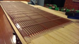
So the panels arc tested just fine so now I'm on to soldering the segment resistors.
Very nice looking stators there. Congrats on successful arc test

Looks like you increased the number of segments in your panels to 33(17 electrical) from the 21(11 electrical) you used in your first stators shown in post #55
http://www.diyaudio.com/forums/planars-exotics/246846-first-time-esl-builder-6.html#post3757543
I don't recall you mentioning a particular reason for this change. Was there one?
- Status
- Not open for further replies.
- Home
- Loudspeakers
- Planars & Exotics
- First time ESL builder