Sorry for duplicating this question; I have asked it in the main isolator 'something cool'thread but it is a but quiet there.
I have recently received an Ian iso board but I get lots of distortion/noise through it. Altered the jumpers as I have a hifiberry dac+pro (master mode). I have followed the power up procedure. Tried a battery pack....I suspected this so swapped for Rpi supplied wall wart smsp. Still same noise.
Any help please?
Thankyou
Last edited:
Simon I believe it is signal dependant distortion. Not a general psu/mains type hum. I shall do some more observations.
Thanks for the offer of reference
I once had the same problem. It turned out I had the jumpers for the master mode in the correct postion but upside down.
I once had the same problem. It turned out I had the jumpers for the master mode in the correct postion but upside down.
Not sure I understand how these could be upside down but having checked they appear to be correctly oriented
If I Power my 9038Q2MPi voltage rails separately, do I skip connecting the 3.3v @ J3?
I'm thinking so, just checking.
Thanks,
Aguaazul
Nope, Need to power J3 too. Bit now the LOCKR & LOCKL Are red, no sync.
For anyone interested in possibly trying film caps for output stage +-15v power filtering to get rid of any remaining opamp graininess, good news that some low priced ones have been found to work well: https://www.diyaudio.com/forums/digital-line-level/314935-es9038q2m-board-448.html#post5793282
It has been a few days of delay while I rearranged things to do some more power supply testing. The 6v electrolytics have been removed from the dac board and now all three TP Trident-SR 3.3v (ADM7150) regulators are running from 6.7v input power. The AVCC regulator also has a 33-ohm, 1/2-watt resistor from the output to ground.
Another change from the last report is that the +5v supply for the clock board is now from a Chinese LT3042 w/pass transistor PCB (with the large electrolytic filter cap having been replaced with a Nichicon 10,000uf, 35v, FW(M) type).
There are 3 different +-15v regulator boards to try before I have to change the test setup very much. The first +-15v supply is a TP Placid-HD. It sounds grainy, but as is typical in such cases 100uf of mixed value Wima mks4 film caps added from each of the 15v rails to ground fixes that and make the sound very smooth. Users of that regulator might want to give the film caps a try.
The dac is sounding better than at last the listening report, particularly with the +-15v film caps added.
The other two +-15v regulators I have yet to try include: (1) a Jung-Didden regulator based on the PCBs sold in the diyaudio store, and (2) a Seltzer regulator based on a PCB and schematic sold by ATL. Hopefully, it will be possible to try both regulators with and without film caps, without inducing any instability from the film cap load impedance. I will report back with more listening results as I find out more.
(Note: Some descriptions of prior testing and a picture of the test setup can be found in posts #357, #322 and #336. One thing I didn't make clear at first is that all output stage opamps are OPA1612)
Last edited:
Good afternoon.
Further to my noise issues....it plays fine if I 'cast' Spotify to Moode, but try to play one of the radio stations in Moode itself and it's all noise over the music. There is noise without signal.....for instance on the left/right channel test clip that is on the SD card with the Moode OS, when the guy is saying 'this is the right channel', there is still noise from the left channel.
Sat here with Spotify playing fine?
@jimk04,
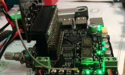
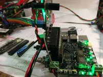
Please post pix of your setup including closeups of the jumper settings. Ian posted about his tests of the HiFiBerryDAC+Pro in master mode in post 139 of the isolator thread. I don't remember if I tried that DAC on the IsolatorPi, but I do know I tried both versions of Allo.com's Boss on the IsolatorPi and they worked well.
So we know that the IsolatorPi does work for DACs in master mode. Now we just need to find out why its not working in your setup. AND as yet, we don't have sufficient info to do that.
Thanks!
Greg in Mississippi
Another slight improvement to report on: The optional output stage caps C9,C10, C19, C25 have been populated with 5600pf C0G. With the new caps, the Crystek clocks now sound brighter than before, perhaps because less HF/RF junk from the dac outputs getting though and causing distortion in the differential summing stage and or the external headphone amp (Crystek 957 clocks still sound more accurate than NDK SDA). Cymbal sounds are finally starting to reveal more details of the actual sound on the recordings, although there is still distortion that needs to be addressed. My guess at this point is that clocks themselves should be on a dedicated regulator located as close as possible to the clock sockets. Another ADM7150 board has been ordered to give it a try. Probably work best with the regulator input voltage set to >=6.7v (as seems to be the case with the other ADM7150 boards). The other thing to do is harmonic distortion compensation, and generally checking an FFT for any problems. Since it is pretty inconvenient to inject test signals from RPi, I will plan to hook up the FIFO_Pi to a USB board for the next phase of testing.
In summary, at this point it is still no Allo Katana (used with appropriate power supplies), say, for high quality 16/44 CD audio. However, its starting to look more like it might be able to get to that point with a bit more work. If distortion can be cleaned up as much as possible, then the interesting thing will be to try sending native DSD512 from HQPlayer via USB. That usually gives pretty much the best sound from one of these ES9038Q2M dacs diy'ers know how to do (assuming all the surrounding circuitry is working up to the level it should be). With DSD512, there is a good chance this dac may be able to sound better than is possible with Katana.
In summary, at this point it is still no Allo Katana (used with appropriate power supplies), say, for high quality 16/44 CD audio. However, its starting to look more like it might be able to get to that point with a bit more work. If distortion can be cleaned up as much as possible, then the interesting thing will be to try sending native DSD512 from HQPlayer via USB. That usually gives pretty much the best sound from one of these ES9038Q2M dacs diy'ers know how to do (assuming all the surrounding circuitry is working up to the level it should be). With DSD512, there is a good chance this dac may be able to sound better than is possible with Katana.
Last edited:
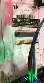
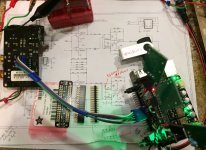
Turns out there is something else that helps to clean up the sound. I separated the dac board from the FIFO board using a right angle adapter I soldered together. There must be some stray clock noise coupling into the dac board or something similar from the two boards normally being so close together. It definitely helps clarify the sound another notch to separate them. Other stuff still needs to be done too. Pics below.
Attachments
If you power the three rails separately then no need to power J3. Have you cut the IN pins of the three capacitor mini-tabs? Note that there are two IN pins per tab, one marked along with the GND and OUT, and the other located at the opposite end unmarked.
I think some of the rails in your setup are not receiving power correctly.
I think some of the rails in your setup are not receiving power correctly.
Nope, Need to power J3 too. Bit now the LOCKR & LOCKL Are red, no sync.
@Markw4,
Thanks for taking the time to delve into Ian's GB gear and look at how to get the best out of it using more traditional power supplies than the GB LiFePO4 supply.
To help get a feel for how these options compare to Ian's LiFePO4 supply (and his developmental UCPi), I spent some time yesterday and prepared some ADM7150 regulators (using Acko's older AKR75 boards). While it is not next on my list of trial with Ian's GB gear, one of my end-point setups will be to cut the traces and separately power the GB DACs rails via separate various regulators (likely ADM715x and paralleled LT304x), multiple separate LiFePO4 cells (I have 2 of Ian's battery boards here with one setup for 4 separate 3.3V rails so I can do this), and Ian's UCPi (in advance of his full Ultracap supply). In the meantime, after a bit more work on customizing the IV filtering to my tastes, I'll be trying board-mounted mid-sized ultra/supercaps. AND many thanks to @wlowes for trying those and reporting on them AND @jacklee for pointing out what is needed to cut the input traces to seperately power Ian's DAC card rails.
Some thoughts on your recent posts...
- On what you are hearing and theorizing as possible RF interference, can you try a different power supply for the RPi? I'm currently using a good linear supply that I use as my baseline supply for my SBC sources based on the K&K Audio low voltage supply. I pulled out an 5V iFi iPower I have here and used it to power the RPi. In my setup and to my ears the highs got courser and a bit edgy and the overall sound was less listenable. Basically, with the linear supply in, I wanted to listen more... with the iPower in, I wanted to take it out as soon as possible! I tried it multiple times across four separate days and got the same results each time. I wonder if you'll hear less of what you're suggesting is RF with a good linear supply? I TOTALLY agree with @wlowes comments on the importance of the power to the RPi and I'm getting ready to try Ian's stack on one of my modified RPi 2B's with linear regulation replacing the on-board DC-DC converter power management chip for the 3.3V and 1.8V rails. I do need to say I'm not pooh-poohing your comments, but I DO think a good linear supply will make a difference in that area. Also, remember the metal shield Allo put around the clocks on the Katana DAC board? Something similar may be worth considering.
- On adding the optional filter C's on the IVStd, interesting that you used 5600pF instead of the recommended 3800pF. What were your thoughts there? Also, did you consider changing the filter C values on the IV stage instead? I chose that as my first place to focus thinking that cutting the out-of-band frequencies early would make things better for both that stage AND the following one. I'm at 1500pF now replacing the stock 270pF filter Cs in the IV stages along with the Rasmussen-style pre-IV filtering that Allo uses on the SQ Opamp board. I suspect with that pre-IV filtering, I might be able to use a 1200pF for the IV stage filter Cs with good effect.
- A related question... why are you using the SE output? Doesn't your amp have balanced inputs? I'm currently running the balanced outputs on all of the stages I'm running and in the case of the IVStd and Ian's prototype IV1632 I have here, I haven't even installed an opamp in the SE summing stage position on either.
- Thanks for your thoughts on regulators, especially the pre-load trick (again, I remember using that from the 80s... effective with the LM317/337 pairs of the day... was that from Dick Marsh? I MAY have gotten that from him back in the day.) and feeding even LDO regulators with higher than typical voltage for better sound (when using my AC-connected supplies, I typically feed ADM715x & LT304x regulators with roughly 11V raw DC).
- Related, when you were trying different input voltages with the ADM7150 Tridents, what was the highest you tried and what did you hear with that compared to your preferred 6.7V? I ask as mine will be fed from my roughly 11V raw DC supplies which I can't easily adjust, but if needed I can add another regulation stage between. BTW, as I mentioned before, my TP AVCC SR does use the adjustable ADM7151, but I checked and my Trident SRs use the low-voltage-input-only ADM7154. SO your comments on that should warn those inclined to experiment.
- Though I don't have a schematic for the FiFoPi, as far as I can tell it DOES have an almost dedicated regulator for the clocks, U9, an LT3042. Poking around with my meter, I only see it being used to power the clocks AND the IC nearest to the I2S output u.FL (which I haven't tried to identify). I thought it was the final I2S reclocking buffer, but that appears to be the somewhat larger IC next over right next to the clock position closer to the center of the board. THAT IC appears to have a small LDO right next to it. AND almost in the center of the board is another LDO, an LP5907. It's possible that the LT3042 feeds one of the BGA processing chips since I can't probe them, but I doubt... I suspect Ian' too thoughtful of a designer for that.
- On graininess, I'm not noticing any with the LiFePO4 supply powering the stack when I'm using an active IV stage.
- On your RPi setup, based on your pictures, I'm guessing you are using an RPi 3 with the built-in WiFi for control access and playing music off the USB stick attached to the unit. Correct? OR is your setup different? IF you're using an RPI 3 with the built-in WiFi, I wonder how much that might be contributing to RF? Although Soundcheck's recent article about going to WiFi instead of wired is intriguing & I plan to try it at some point as I have a couple of RPi 3s here, mainly to compare to my standard 2Bs. I'm currently using only RPi 2Bs to avoid the WiFi and potential RF interference. In each of my setups, I use a dedicated audio-system only network that doesn't connect to the internet. I even go so far as to have an optical link as my final devices before the RPi to break all electrical connections to the computer and networking HW except that final FMC. I'm using the Logitech Squeezebox-styled setup with the RPi running PiCorePlayer / Squeezelite and my music on a dedicated LMS music server.
- I haven't forgotten about trying the IVStd with higher value R's, though the resistor values on Ian's IVStd are not wildly different than those on the Allo Katana output stage. BUT that'll mean getting another bare board from Ian and building it up at some point. That's a ways out.
- Thanks for considering an Arduino solution for the distortion compensations adjustments. I'm going to approach Ian about doing that with his existing controller, but in case he can't, I'll be very interested in your solution. I'm NOT the person to try it out, I have no Arduino experience.
I'm sure I forgot something I wanted to include, but I'll follow up when I remember.
Greg in Mississippi
Last edited:
If you power the three rails separately then no need to power J3. Have you cut the IN pins of the three capacitor mini-tabs? Note that there are two IN pins per tab, one marked along with the GND and OUT, and the other located at the opposite end unmarked.
I think some of the rails in your setup are not receiving power correctly.
Thanks Jacklee. I completely removed the capacitor boards. Will double check the wiring.
@Markw4,
Thanks for taking the time to delve into Ian's GB gear and look at how to get the best out of it using more traditional power supplies than the GB LiFePO4 supply.
You are quite welcome. I hope the info may be useful for others using line power, or perhaps for other Sabre dac projects.
In more recent developments, I have tried a couple of other AVCC regulators, both from TP. One is the old original Trident AVCC dual regulator using an opamps and pass transistors. The other TP regulator is the 3.6v dual ADM7150 Trident-AVCC which appears to have more filtering than the standard 3.3v Trident-SR regulators.
Both of the above TP regulators sounded brittle (digititus) as first, the old version being a little bit worse. The new Trident-AVCC sounds much better with a 39-ohm, 1/2-watt load resistor. I think I will stick with that regulator for now, but probably an opamp-only regulator (as recommended by ESS) should be tried too (which is what I use on my other ES9038Q2M dac projects).
...can you try a different power supply for the RPi?
...
I may have a linear supply I could use, but I will have to make sure it can handle the current. In the meantime, I just used a straight-long-pin 40-pin socket to raise the FIFO_Pi board away from the RPi board. The right angle adapter is still between the FIFO_Pi board and the dac board, and that's where I noticed an improvement that I would guess was due to some stray coupling with those boards too close together. I would agree some combination of shielding and using multilayer boards can help keep unwanted stray coupling to a minimum. A shield alone can be hard to do well since connection with a wire to ground somewhere would add a lot of series inductance. A wide strap of copper would probably make a better, more effective ground at HF/RF.
- On adding the optional filter C's on the IVStd, interesting that you used 5600pF instead of the recommended 3800pF. What were your thoughts there? Also, did you consider changing the filter C values on the IV stage instead?
The feedback caps on the I/V converters is probably not the best place for filtering RF junk, since it relies on opamp loop gain to work and loop gain falls off at HF. A cap to ground is only limited by its self-inductance and the inductance of a via to ground (if a via is used).
Also, adding any resistance in series with the dac outputs will increase distortion, so no way I would do that. A cap alone across the dac +- outputs for each channel is okay though, and likely a good idea. Probably the cap should have some ESR, so if C0G were used, a small resistance might go in series with the cap. We don't want it resonating with parasitic inductance as the combination is excited by dac switching transients.
- A related question... why are you using the SE output? Doesn't your amp have balanced inputs?
My HPA does have balanced and unbalanced inputs. The balanced inputs have slightly more audible distortion due to the unbalancing receiver inside the HPA (probably a THAT Corp. balanced line receiver). In most cases where internal circuity inside an audio device is SE (such as is the case with my HPA) it usually sounds better (more accurate, less distortion) to use SE rather than balanced. The reason balanced sounds better sometimes is because ground problems exist somewhere and they become audible when SE is used. I use what might be considered a cheat when I am doing testing (like with this dac). I get AC power from a Monster HTPS Mk II power conditioner, which is really excellent for isolating AC grounds between audio devices plugged into different AC output groups. At the same time it keeps ground impedance back to the AC line ground very low. Clever use of transformers inside do the trick. For that reason I don't have ground problems when using multiple power supplies and a computer for testing. Thus, I am free to enjoy the lower distortion of SE interconnections without penalty (aside from the cost penalty of acquiring the power conditioner on ebay).
...was that from Dick Marsh, I MAY have gotten that from him?
Could be. He did a lot of clever work back in the day. He was also the principle designer of the Monster power conditioner I use. How do I know? He told me, he lives maybe 30 minutes from here over a mountain to the east. I go to visit with him now and then, and we converse about audio design (among other things).
- Related, when you were trying different input voltages with the ADM7150 Tridents, what was the highest you tried and what did you hear with that compared to your preferred 6.7V?
<Regarding ADM7151, ADM4154> your comments on that should warn those inclined to experiment.
On the warning issue, I did warn once or twice in earlier posts, but not sure if I need to repeat it in every post that mentions the input voltage. It is why I always try to say 'ADM7150' rather then just saying 'Trident.'
Regarding input voltage, I didn't hear much difference from going any higher than 6.7v and I wanted to the regulators not to run too hot (especially with an added load resistor). When I get around to doing FFT tests, if I find raising the input voltage any more is helpful then I will post about it.
Though I don't have a schematic for the FiFoPi, as far as I can tell it DOES have an almost dedicated regulator for the clocks, U9, an LT3042.
Could be, I haven't looked yet. Could be the regulator would work better on 6.7v input, don't know. That is part of what I had in mind using an external regulator. Since I don't have a schematic and Gerbers for FIFO_Pi, I don't know what the existing circuitry looks like (and layout is part of the circuitry, not just what is shown on a schematic, IMHO).
- On graininess, I'm not noticing any with the LiFePO4 supply powering the stack when I'm using an active IV stage.
Maybe not, but having a stack of parallel film caps to use for testing can be very useful. One may not think there is a problem, then be really impressed with the sound quality boost when film caps are added. So far, I haven't found a case where they don't help dac output stages, but I haven't tried the Jung-Didden regulator yet either. It just might do the trick without added caps, but then again it also costs as much or more to build compared to a stack of parallel film caps. Also, I need to try a Nazar regulator of the type eziitis recommends. That might do the trick at lower cost, but I would need to see for myself before I could recommend it.
- On your RPi setup, I'm guessing you are using an RPi 3 with the built-in WiFi for control access and playing music off the USB stick attached to the unit.
Correct. Well, I will find out how different using a good galvanic isolated USB to I2S board and Windows is instead of using RPi. If it sounds better then that would be a reason to investigate RPi more.
- I haven't forgotten about trying the IVStd with higher value R's...
It is still something I have in mind to perhaps try at some point. Have to look at an FFT first to see what is going on from that perspective. I did notice the dac has the usual ESS 'hump' in distortion at lower levels. One can turn down the dac and turn up the HPA gain instead. It is audible that the harmonic distortion increases and gets brighter on things like vocals.
- Thanks for considering an Arduino solution for the distortion compensations adjustments. I'm going to approach Ian about doing that with his existing controller, but in case he can't, I'll be very interested in your solution.
I will probably try it before too long. No rush, just one of the things that has to be done eventually in order to get to the best sound quality possible, but it also means a notch filter will be needed. Maybe Ian can make one of those too. Not hard to do, and probably more people would want to buy one from him rather than build one from scratch.
Last edited:
Great info as always Greg. Re the IC near u.Fl ...It is marked 533 and I believe is an output buffer for mclk. I depend on mckl for the I2StoPCM.- Though I don't have a schematic for the FiFoPi, as far as I can tell it DOES have an almost dedicated regulator for the clocks, U9, an LT3042. Poking around with my meter, I only see it being used to power the clocks AND the IC nearest to the I2S output u.FL (which I haven't tried to identify). I thought it was the final I2S reclocking buffer, but that appears to be the somewhat larger IC next over right next to the clock position closer to the center of the board.
Greg in Mississippi
So, I added a BG HiQ .47uF cap to pins 1 & 4 (VCC and Grd). It really cleaned up final smearing of sound and made cymbals sound like the real deal.
Interesting, you kknow you're getting old when suddenly the old tricks that the old timers knew are popping back up again. Walter Jung showed in tests how the 317/337 performed better when preloaded with some current (100ma or so I recall), I know the results were published in one of his early work on measuring output impedances in power supplies.
Last edited:
- Home
- Source & Line
- PC Based
- IanCanada's Latest RPi GB Goodies Impressions... and your tweaks, mods and hints...