@soundcheck,
@ichiban, with the early ESS DAC chips (ES9008 & ES9018), you could set the DAC to run in sync mode by feeding a clock that was from the same family as the source material and the DPLL would not do the typical asynchronous upsampling... I heard the term 'free-wheeling' used, as I remember.
You can still do that with the current generation ESS DAC chips (ES9028PRO, ES9038PRO, ES9028Q2M, ES9038Q2M). That is what you get with one of Ian's DACs when you connect the MCLK output from the FiFoPi and turn off the local clock using the small switch on the DAC board. Once you have done this, you can also use Ian's ESS Controller to set the PCM and DSD DPLL Bandwidth to the lowest level 1.
BUT these new chips also offer a more advanced version of sync mode, true sync mode. This is where you actually disable the DPLL entirely. Ian's controller also allows you to do this. BUT there are limitations:
- PCM only, no DSD
- MCLK should be 128FSR for best results. For 44.1 source, that is a clock of 5.6488! While you can use the more common 22.5792 or 44.1584 clocks and it will work, you are not getting the full benefit of full sync mode at that point.
Still, even with the wrong clock frequencies, I personally prefer full sync to sync and sync to the typical ASRC mode.
Greg in Mississippi
Greg,
Thank you very much for the information. 🙂
-ICHI
@Greg, any others,
Looks like the dac I2C bus is idle most of the time except when status changes in volumio or when input to Ian's controller occurs. That being the case, it might be very simple to hook up an Arduino to adjust harmonic distortion compensation without disturbing the existing Ian dac controller. I will probably go off and do it on my own because I want the dac to sound as good as it can. If others are interested, we could make it more of a group effort.
Looks like the dac I2C bus is idle most of the time except when status changes in volumio or when input to Ian's controller occurs. That being the case, it might be very simple to hook up an Arduino to adjust harmonic distortion compensation without disturbing the existing Ian dac controller. I will probably go off and do it on my own because I want the dac to sound as good as it can. If others are interested, we could make it more of a group effort.
@ichibon, you are welcome. Glad that helped.
@soundcheck & @ernesternest, I have one of the Audiophonics 8xTDA1387 RPi DACs too. Best to take further discussion on those to one of the threads discussing DACs using that chip... there are several here including a couple of DIY projects, one of which I've heard here too.
@Markw4, interested in the Arduino solution. I'll also be approaching Ian on that once he is back from vacation. AND take a look at what DimDim has done.
Also saw your comments on the resistor values on the IVStd. I just finished populating the resistors on a couple of the bare boards... if you send what you prefer there, I'll get another from Ian and build it up to try.
Greg in Mississippi
...if you send what you prefer there, I'll get another from Ian and build it up to try.
Increasing resistor values would require reducing capacitor values by the same factor, if the same corner frequencies were to be preserved. There are a whole range of possibilities for changes. Usually it is easier to find resistor values than capacitor values, so scaling the caps down in value would probably come first, according to what NPO/COG/SMD_film cap values are available. After that resistors can be scaled up by the same factor.
I would prefer to see resistors that at least limit the loading on any opamp output to not below 600-ohms at any frequency. Higher resistance values should be safe.
Resistor matching between channels is important to minimize distortion, so tighter tolerance parts are better, say, good quality .1% or better thin film resistors.
Regarding noise, it is signal vs noise that matters. Once the signal is up at a reasonable level (say, 1 volt or more), then heroic noise minimization is often much less of a concern.
For a possibly more challenging alternative to re-scaling existing parts values, the output stage design we have been using over in the ES9038Q2M board thread sounds good to at least some people. There might be less loading on the opamps than they can handle, and more noise than the minimum, but you might try that and see what you think (assuming you can patch around the existing board traces for the slightly different topology.
Along with trying at least somewhat larger value resistors, I would be inclined to try changing the Vref divider on the back side of the output stage board so that it produces AVCC/2, rather than AVCC/3. In theory that should be where dac common mode distortion should be the least.
...interested in the Arduino solution...
Thought it best to reply separately on the above issue.
I have been using Arduino as an I2C bus controller for awhile now (for various types of chips, including ES9038Q2M). What would be helpful to know is where everyone else is at on that subject. In other words, do I have to do all the work? How much explaining would be needed? Those kinds of things.
Also, it may help to know I tend to use pretty minimalist code for my experiments. I haven't been designing a complete diy project ala Dimdim. Don't like programming enough for that. It means people have to be willing to learn about low level register programming if doing things my way. I am always happy to answer technical questions and explain what I can.
Of course, maybe Ian will have a solution and things will kind of take care of themselves.
Last edited:
@soundcheck,
I prefer the minimum-phase slow and have since the early Katana.
That's even worse than Apodizing by looking at that awful frequency response.
For sure it's great to cover up any flaws in the upper registers though. 😉
If all your systems are tuned based on that filter...
And regarding TDA1387. Hold your horses!
My intention was not to highjack this thread. It was simply a response to Ians remark about challenging all other DACs out there.
I just outlined my impression that the whole Sabre hype might lead into a questionable direction.
I never did and do not have any intentions to discuss that 1387 DAC over here.
Last edited:
I thought your comment was appropriate. A core component of this GB is FIFO pi which can be used to feed any DAC. Many including myself have commented that FIFOpi delivers very strong performance from the Rpi on par with other excellent solutions based on BBB. I don't think that is off topic for a thread that examines FIFO Pi and a suite of attached devices. It is an important point to focus efforts on the downstream devices if there are opportunities for improvement in sound.And regarding TDA1387...
My intention was not to highjack this thread....
What results have people had from adding a super cap to each of the rails on the fifopi? Anyone done it on the plain ldo bypassed rails without adding an external reg?
Baby steps...
Baby steps...
Not yet
I am taking it one cap at a time and letting them burn in for a week. First few days are awful, but don't give up.
I have one on the rail of the 45mHz OX. Excellent. Another on the clean supply to FIFO but not bypassing the onboard LDO. Also excellent.
The latest is a big one on the dirty power supply of FIFO. It too has a linear supply. It took awhile to burn in. Smaller impact than the others but I think adds.
Next will be one on the main pcb (after the LDO). But not for a couple of weeks. I want to just enjoy some music.
@Supersurfer, did you discuss this with Sparkos? Did they have any input?
Greg in Mississippi
No I didn’t. My time is limted and I just ordered a new opamp.
It arrived today, listening to it now, not bad new out of the box, lets see if these hold up during the burn in period........
Thought it best to reply separately on the above issue.
I have been using Arduino as an I2C bus controller for awhile now (for various types of chips, including ES9038Q2M). What would be helpful to know is where everyone else is at on that subject. In other words, do I have to do all the work? How much explaining would be needed? Those kinds of things.
Also, it may help to know I tend to use pretty minimalist code for my experiments. I haven't been designing a complete diy project ala Dimdim. Don't like programming enough for that. It means people have to be willing to learn about low level register programming if doing things my way. I am always happy to answer technical questions and explain what I can.
Of course, maybe Ian will have a solution and things will kind of take care of themselves.
I have written Arduino programs in the past, but I have a HW background so am a pretty brute force type programmer.
But after spending a little time looking into what's out there, seems like using Dim dim's hifiduino code and setup may be the best option.
Don't want to reinvent the wheel if I don't need to.
...after spending a little time looking into what's out there, seems like using Dim dim's hifiduino code and setup may be the best option.
Would someone out there be willing to try it?
Would someone out there be willing to try it?
I'm probably 2-3 months before I have anything running.
And be a while before I decide for sure what I want to do for controlling the dac.
Here is a url to dimdim's project.
TFT HiFiDuino Pro Project | Dimdim's Blog
Looked a little more at it.
The easiest way would be to buy the adapter board he sells to add the Arduino peripherals required. I've hardwired Arduino projects by hand in the past, but its a pain.
And you need to wire a led lock signal to gpio4. The dual mono dac has two lock leds. I'd pick one to use, and figure they should be in the same state. Otherwise need to add an and gate to make sure both dacs are locked.
Way harder than just plugging in Ian's controller, but seems to give you full control of the registers. And you have the source code so changes/additions/customizing is possible.
Other advantage is no need to worry about contention on the i2s bus if you add a processor to it, but I don't know if this is a real concern or not.
Randy
And you need to wire a led lock signal to gpio4.
Why is that? Lock status can be read from a dac register and or a dac chip GPIO pin can be programmed via I2C bus to act as a lock status indicator output. Either way, some I2C controller activity would be needed to make lock status knowable.
Why is that? Lock status can be read from a dac register and or a dac chip GPIO pin can be programmed via I2C bus to act as a lock status indicator output. Either way, some I2C controller activity would be needed to make lock status knowable.
Copied from Dimdim's blog
The GPIO4 line is very handy to have, since it provides feedback to the controller whenever a lock/unlock condition happens or when the sampling rate changes, but the code could be adapted to work without it (like the original (TFT) HiFiDUINO code did, polling the DAC every couple of seconds to see if anything has changed).
So you can poll, but the code as running now looks at the gpio to determine lock status.
or add a wire from a lock led to the gpio pin and run the code as is.
Fitted OPA1612 tonight, that's much better a big improvement. Definitely heading in the right direction now. Clocks and supercaps next.
Just tried the Crystek 957 clocks instead of NDK. Sounds closer to right to me, although still some remaining sound quality problems.
Cleaning up remaining distortion should help a lot. Now it sounds more like IMD rather than jitter, as the bigger problem. The sound seems a bit muffled and jumbled together in the midrange which sounds like a lot of HD/IMD contributing to that. But adding artificial brightness and pseudo-clarity from NDK jitter is not the fix, it just adds another problem.
Harmonic distortion compensation should probably be the next thing to look at. If an FFT shows much in the way of higher than 3rd harmonic, then some hardware troubleshooting would be necessary.
To summarize configuration so far:
*DVCC on ADM7150
*VCCA on ADM7150
*AVCC on NewClassD UWB2 (with 5.7v regulator powering dac board)
*Output stage +-15v using parallel film caps from each rail to ground (10+10+33+33+33, all values uf, Wima mks4)
*Output stage on ribbon extender to help attenuate RF leakage into output stage
*Crystek 957 clocks, rather than NDK.
Note: Still on my to-do list:
*Test ADM7150 with a 33-ohm 1/2-watt resistor to ground to see if that makes it more usable for AVCC (or otherwise improves SQ elsewhere).
*Try adding C9, C10 to output stage board (NPO or C0G).
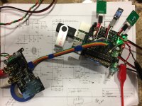
Also, checked I2S signals on clean 40-pin GPIO bus. Don't know why termination resistors would be needed. Pic of BCLK below.
To follow up a bit on my previous post above: Tried both ADM7150 and UWB2 regulators with 33-ohm load resistors for AVCC. Both sound better that way, or maybe the AVCC circuitry inside the dac likes the 33-ohm resistor there. Either way, it helps improve sound quality.
UWB2 sounds a little softer on the transients than ADM7150, but it also seems a bit more forgiving of distortion (all dac board regulators still supplied with 5.7v in order to bias on UWB2, but not exceed board filter cap voltage rating).
For the next test, I separated the AVCC regulator from dac board 5.7v supply and connected that one regulator to a variable supply. Didn't want to get the regulators too hot since they were both supplying 100ma to the 33-ohm resistors mounted on them, so avoided raising the input voltage very much. Found that both regulators sounded better and SQ was less distorted with regulator input voltage increased to 6.7v. With the input voltage increased, ADM7150 turned out to produce the best SQ, it was both tight and punchy as it should be for the music that was playing, and it also provided for the lowest distortion I have heard so far out of the dac.
I really think its time for harmonic distortion compensation at this point. The dac is getting much closer to producing acceptable SQ for my testing purposes. Depending on how much HD comp. can help, it may be okay to leave the output stage as-is (on the extender cable). Otherwise, the output stage will be the next thing to get attention.
Attachments
Last edited:
Today i installed the OPA1612, this is probably having the biggest impact, so before start modding plug them in first.
I have now fitted the :
- NDK Clocks like them better than Crystek
- Added a supercap on the DAC board supply 0.33F
- AVVC bypassed with a Sanyo Oscon
- Added to Elma Slimic to the +- Supply Lines of the Output board
- Replaced Opamps with OPA1612
I am quite happy with the sound now need more time to compare it to my other gear ...
Replaced Opamps with OPA1612
The was the first thing I did, too. Forgot to mention it my configuration summary a couple of posts above. The Brown Dog dip adapters can be seen in the pic 🙂
- Home
- Source & Line
- PC Based
- IanCanada's Latest RPi GB Goodies Impressions... and your tweaks, mods and hints...