Thank you Aleph5
I barely hit the send button as I realized there are more differences between wiring scm and FE.
Have these been sorted out already?
I barely hit the send button as I realized there are more differences between wiring scm and FE.
Have these been sorted out already?
I think the colors and gauges are off, but otherwise it was correct for me. I ended up leaving the O+ connections to the PS board off, for a couple of reasons. If you wire them, I don't think they need to be 18 AWG. Without, there is only a single thump right at turn-on, not too objectionable.
I might try posting some suggestions for colors and wire lengths, but no promises if and when. Sorting that out took me the longest amount of time.
P.S. I'm referring to the wiring diagram by Nelson in the N-ch PDF, not in the build guide which was for the P-ch.
I might try posting some suggestions for colors and wire lengths, but no promises if and when. Sorting that out took me the longest amount of time.
P.S. I'm referring to the wiring diagram by Nelson in the N-ch PDF, not in the build guide which was for the P-ch.
Last edited:
Ah yes!
Nelson's updated doc made it all clear!
As 6L6 put it in his guide, the wires colors aren't anything but colors 🙂
Now comes the tedious part, putting the whole together, making sense, a nice layout and more importantly, no goof!
Nelson's updated doc made it all clear!
As 6L6 put it in his guide, the wires colors aren't anything but colors 🙂
Now comes the tedious part, putting the whole together, making sense, a nice layout and more importantly, no goof!
Oh I'm chill just wanted a second opinion.
Last thing I want to do is let the smoke out of the 2SK82.
Thanks for the feedback!
Last thing I want to do is let the smoke out of the 2SK82.
Thanks for the feedback!
A Test and Review of the Theseus-PSFilter Board for Sony N-Channel VFET Amps
I finished the Sony N-Channel VFET amp a few weeks ago (#138). I like it very
much but one thing I noticed right away was that when turning the amp off, I
would get a fairly loud pop from the speakers. It wasn't really the typical
bass thump but had a very sharp attack, sort of like a higher pitched snare
drum hit. I haven't noticed any thumps or pops when turning the amp on.
Mark Johnson was kind enough to supply me with one of the Theseus-PSFilter
boards for testing to determine how it would affect the turn on and off
thumps/pops.
See post #461 for an introduction to the board.
On the board provided, the 10 sec. jumper (third quickest, I think) was
installed by default. I didn't change it. I was careful to not touch the high
impedance areas of the board at all during the installation.
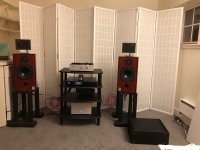
In this case, the amp is connected to KEF Calinda speakers for which the specs
say they are only 83 dB/W at 1 M efficient. The preamp is a B1-K. The amp is
also plugged in via a wifi smart plug.
After installing the board and powering up the amp, I heard only the relay
click from my DAC. I heard nothing from the speakers. The sound output to the
speakers was muted, it could be heard very, very faintly, for about 12 or 13
seconds then, it unmutes and plays at normal volume. I can't remember if there
was sound at normal volume with the original board immediately after turning it
on. I think there was.
I tried turning off the amp after a few minutes and the pop I heard was greatly
reduced. It wasn't much more than a blip where with the original filter board,
it was loud percussive pop or rap. It was turned off via the wifi smart plug
that time.
After listening to the amp for about 12 - 15 minutes, a sharp pop occurred and
sound was muted for about 5 seconds and then came back on. It hasn't done that
again since. I don't know what caused that.
After letting the amp run for another 50 - 60 minutes, I tried some more power
ups and power downs. When powering up or down with the wifi smart plug, I don't
hear any thumps or pops at all on turn ons. On turn offs, I hear the faintest
of pops, not worth even thinking about. When powering up and down with the rear
switch, no pops are heard at all.
Thank you, Mark. Nice work!
I finished the Sony N-Channel VFET amp a few weeks ago (#138). I like it very
much but one thing I noticed right away was that when turning the amp off, I
would get a fairly loud pop from the speakers. It wasn't really the typical
bass thump but had a very sharp attack, sort of like a higher pitched snare
drum hit. I haven't noticed any thumps or pops when turning the amp on.
Mark Johnson was kind enough to supply me with one of the Theseus-PSFilter
boards for testing to determine how it would affect the turn on and off
thumps/pops.
See post #461 for an introduction to the board.
On the board provided, the 10 sec. jumper (third quickest, I think) was
installed by default. I didn't change it. I was careful to not touch the high
impedance areas of the board at all during the installation.
In this case, the amp is connected to KEF Calinda speakers for which the specs
say they are only 83 dB/W at 1 M efficient. The preamp is a B1-K. The amp is
also plugged in via a wifi smart plug.
After installing the board and powering up the amp, I heard only the relay
click from my DAC. I heard nothing from the speakers. The sound output to the
speakers was muted, it could be heard very, very faintly, for about 12 or 13
seconds then, it unmutes and plays at normal volume. I can't remember if there
was sound at normal volume with the original board immediately after turning it
on. I think there was.
I tried turning off the amp after a few minutes and the pop I heard was greatly
reduced. It wasn't much more than a blip where with the original filter board,
it was loud percussive pop or rap. It was turned off via the wifi smart plug
that time.
After listening to the amp for about 12 - 15 minutes, a sharp pop occurred and
sound was muted for about 5 seconds and then came back on. It hasn't done that
again since. I don't know what caused that.
After letting the amp run for another 50 - 60 minutes, I tried some more power
ups and power downs. When powering up or down with the wifi smart plug, I don't
hear any thumps or pops at all on turn ons. On turn offs, I hear the faintest
of pops, not worth even thinking about. When powering up and down with the rear
switch, no pops are heard at all.
Thank you, Mark. Nice work!
Attachments
Thank you SO MUCH for installing this PCB into your VFET amp so quickly, and for posting your honest opinions forthrightly. diyAudio members will greatly benefit from your diligent efforts.
With gratitude,
-- MJ
hopefully some other Alpha testers will receive their boards soon and talk about their experiences too.
With gratitude,
-- MJ
hopefully some other Alpha testers will receive their boards soon and talk about their experiences too.
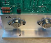
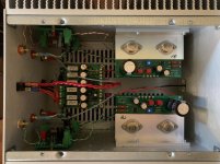
Proud to announce that #143 has been birthed after an uncomplicated labor.
Many thanks to Nelson Pass, Jason, 6L6, ZM and Mark Johnson. Your generosity with your time has been impressive. (as has many others).
The amp sounds great with a musicality and resolution that was surprising for 10 watts. Guess you really only need one really good one.
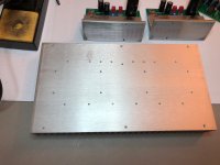
My heat sinks were generally flat but lapped them for good measure.
Had a few observations and questions about amp behavior as mine seems to differ from some already built.
1. Wasn't sure with SMPS if dim bulb tester was necessary. Tried it and learned that the bulb would glow and dim and glow and dim, but SMPS wouldn't operate. SMPS worked fine when dim bulb tester taken out. Should I assume that the protection circuitry in the SMPS might protect some uf us from letting out the precious "magic smoke" that makes all of this possible?
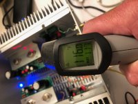
2. Set the bias from Case (drain) of IRF250 to 14V. Was surprised that my operating temp has been much cooler than others. After 10 hours heat sinks are only 120F- Blimey hotish. Could keep my hand on sink for 10 sec or more. Curious if better heat transfer or other reason for cooler operation.
Very glad to hear the positive review re: Theseus, as it has the potential to solve one minor irritation. The vexing turn on and off "thump/pop".
3. Believe that the power supply and switch are wired correctly but have a turn on and off thump pop. Particularly if switch is not switched quickly. Measured DC at turn on with inputs shorted. Will jump to over a volt then drop quickly to less that 400mv immediately then immediately back to nearly 800mVthen drift down slowly to 2-3 mV after several minutes. I'm not sure if the relay is really providing any delay and if I have it wired correctly, although appears like what other have done. Any comment welcome. Also is there any way to change the time constant. Is the time constant simply the product of RC? if so is very short. As I understand it, the resistor will slow the current and then the cap has to charge and then current will be sufficient to power the coil to activate the relay and open up the outputs that are shorted to ground in the "off state". Just seems that this concept should work but I have no delay before music starts.
The DC doesn't really come down all that fast. Might take 15-20 sec for it to come down to less than 100mV. Not sure how low it needs to be to not cause pop.
Also would a different switch have different tendency for thump? Nelson's article designates DPDT switch but seems that the should be DPST. At least that is what I used based on earlier posts.
I feel very fortunate to have had the opportunity to build and enjoy this amp. Was excited for the lottery only to not have my name called in the first or second lotteries. Was only chosen after some "NOT greedy boys" declined. Thanks!.
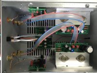
Attached are a few pics for posterity.
Many thanks to Nelson Pass, Jason, 6L6, ZM and Mark Johnson. Your generosity with your time has been impressive. (as has many others).
The amp sounds great with a musicality and resolution that was surprising for 10 watts. Guess you really only need one really good one.
My heat sinks were generally flat but lapped them for good measure.
Had a few observations and questions about amp behavior as mine seems to differ from some already built.
1. Wasn't sure with SMPS if dim bulb tester was necessary. Tried it and learned that the bulb would glow and dim and glow and dim, but SMPS wouldn't operate. SMPS worked fine when dim bulb tester taken out. Should I assume that the protection circuitry in the SMPS might protect some uf us from letting out the precious "magic smoke" that makes all of this possible?
2. Set the bias from Case (drain) of IRF250 to 14V. Was surprised that my operating temp has been much cooler than others. After 10 hours heat sinks are only 120F- Blimey hotish. Could keep my hand on sink for 10 sec or more. Curious if better heat transfer or other reason for cooler operation.
Very glad to hear the positive review re: Theseus, as it has the potential to solve one minor irritation. The vexing turn on and off "thump/pop".
3. Believe that the power supply and switch are wired correctly but have a turn on and off thump pop. Particularly if switch is not switched quickly. Measured DC at turn on with inputs shorted. Will jump to over a volt then drop quickly to less that 400mv immediately then immediately back to nearly 800mVthen drift down slowly to 2-3 mV after several minutes. I'm not sure if the relay is really providing any delay and if I have it wired correctly, although appears like what other have done. Any comment welcome. Also is there any way to change the time constant. Is the time constant simply the product of RC? if so is very short. As I understand it, the resistor will slow the current and then the cap has to charge and then current will be sufficient to power the coil to activate the relay and open up the outputs that are shorted to ground in the "off state". Just seems that this concept should work but I have no delay before music starts.
The DC doesn't really come down all that fast. Might take 15-20 sec for it to come down to less than 100mV. Not sure how low it needs to be to not cause pop.
Also would a different switch have different tendency for thump? Nelson's article designates DPDT switch but seems that the should be DPST. At least that is what I used based on earlier posts.
I feel very fortunate to have had the opportunity to build and enjoy this amp. Was excited for the lottery only to not have my name called in the first or second lotteries. Was only chosen after some "NOT greedy boys" declined. Thanks!.
Attached are a few pics for posterity.
Attachments

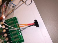
DOH!
I really did it. I managed to reverse Ground and V+ on one of the Frontends.
R7 just unpleasantly fried.
The rest looks unaffected, but that is just upon a first glance.
Anything to test before I attempt a reboot?
I really did it. I managed to reverse Ground and V+ on one of the Frontends.
R7 just unpleasantly fried.
The rest looks unaffected, but that is just upon a first glance.
Anything to test before I attempt a reboot?
What if I haven’t got a diode tester?
Continuity and stuff?
…
Instead of whining I went on and measured Q1 / Q2: both side identical.
Cold sweat, a nicotine-break and a preemptive panic attac, then I'll retry in 4.33 minutes [emoji51]
Some 49 minutes later: benny Goodman’s a string of pearls is playing.
HA!
Me happy, relieved, curious…
Continuity and stuff?
…
Instead of whining I went on and measured Q1 / Q2: both side identical.
Cold sweat, a nicotine-break and a preemptive panic attac, then I'll retry in 4.33 minutes [emoji51]
Some 49 minutes later: benny Goodman’s a string of pearls is playing.
HA!
Me happy, relieved, curious…
hicks! 
😀😀😀
Many many thanks to Nelson, Jim, Mark, Aleksander, Patrick, the forum und überhaupt everyone involved in this fabulous project!
The little bugger plays it's 3rd track: Galak Manis (Balinese traditional stuff, galak manis means "fiercely sweet" or something like that, haha.)
Ah, my lucky number is N° 161
Attachments
Last edited:

3. Believe that the power supply and switch are wired correctly but have a turn on and off thump pop. Particularly if switch is not switched quickly. Measured DC at turn on with inputs shorted. Will jump to over a volt then drop quickly to less that 400mv immediately then immediately back to nearly 800mVthen drift down slowly to 2-3 mV after several minutes. I'm not sure if the relay is really providing any delay and if I have it wired correctly, although appears like what other have done. Any comment welcome. Also is there any way to change the time constant. Is the time constant simply the product of RC? if so is very short. As I understand it, the resistor will slow the current and then the cap has to charge and then current will be sufficient to power the coil to activate the relay and open up the outputs that are shorted to ground in the "off state". Just seems that this concept should work but I have no delay before music starts.
Mine behaves similarly. I'm hoping that others can chime in regarding what kind of delay they are seeing with the current N-channel relay circuit and any mods they have done (besides Mark Johnson's prototype boards) to reduce thumps of pops.
Yup, same for me. No delay with the relay, signal passes to speakers immediately when powered on and DC offset rises to almost 2V.
My cheap and cheerful fix is to use my TC7220 amplifier/speaker selector as a manual mute button. Power up VFET, after approx. 20seconds I push a button to connect speakers, push again prior to powering off VFET.
Guaranteed no thumps or pops this way, just not an elegant solution 😉
My cheap and cheerful fix is to use my TC7220 amplifier/speaker selector as a manual mute button. Power up VFET, after approx. 20seconds I push a button to connect speakers, push again prior to powering off VFET.
Guaranteed no thumps or pops this way, just not an elegant solution 😉
- Home
- Amplifiers
- Pass Labs
- DIY Sony VFET pt 2 (N-Channel Build)