I’m always interested in learning more 😱. Any details to share?
Let me give my understanding: a pentode output has a very high impedance. Without a secondary load the primary will bounce up and down like hell 😱. The voltage can easily go beyond twice Vb. This can lead to some destruction of your output transformer because it very well could arc over and be perpetually short-circuited; also expect aso damage to the tube - the screen grid might arc too... [I even had a 6SJ7 (input pentode) arc between two pins 5/6 at start up.! ]
In a triode I have never noticed it.
With a SIT, we have a triode-like behaviour & that has inherent feedback like a triode, lower internal impedance and well behaved output also without load. Its a different world. Zen like.

my 2 ¢ for what it is worth
i have put one 1000uf Nichicon FG on each rail of the amp board and it seems to have some benefit on the KIcking bass , what value do you use here ?
the best mod for my 16ohm bass driver is definitly the 22R in parrallel with the speaker output ...
the best mod for my 16ohm bass driver is definitly the 22R in parrallel with the speaker output ...
Tears For Fears - Woman In Chains (Official Video) on Vimeo
This song of the band Tears for Fears is not easy to reproduce on the audio system.
We get this huge sound of drums, bass and vocals in forte moments,
me and a friend can hear amplifier~speakers sensitivity limits,
bigger spacey room acoustic is necessary for this type of song as well.
SE Vfet can be the best player in bi-amplified configuration for rock and heavy bass & drum, techno music etc.
Build a kit was a great fun!
Next step if free time I want try build stabilised linear power supply
Using with Headphones
I am using the amp for headphones.
I connected matching transformers (Tango MT-60) to the speaker outs.
The Tango has 8ohm primary and multiple secondary taps.
The sound is impressive. The harmonics and the textures are very fine and nuanced. The top end is especially clear and expansive.
I am using the amp for headphones.
I connected matching transformers (Tango MT-60) to the speaker outs.
The Tango has 8ohm primary and multiple secondary taps.
The sound is impressive. The harmonics and the textures are very fine and nuanced. The top end is especially clear and expansive.
That is interesting. This is the first time I have heard of the VFET amp being used to drive headphones.
Hi TA,
It’s quite a nice headphone amp, even direct drive - no transformer needed. It’s quiet enough to be a headphone amp that’s for sure. You might have missed this:
DIY Sony VFET Builders thread
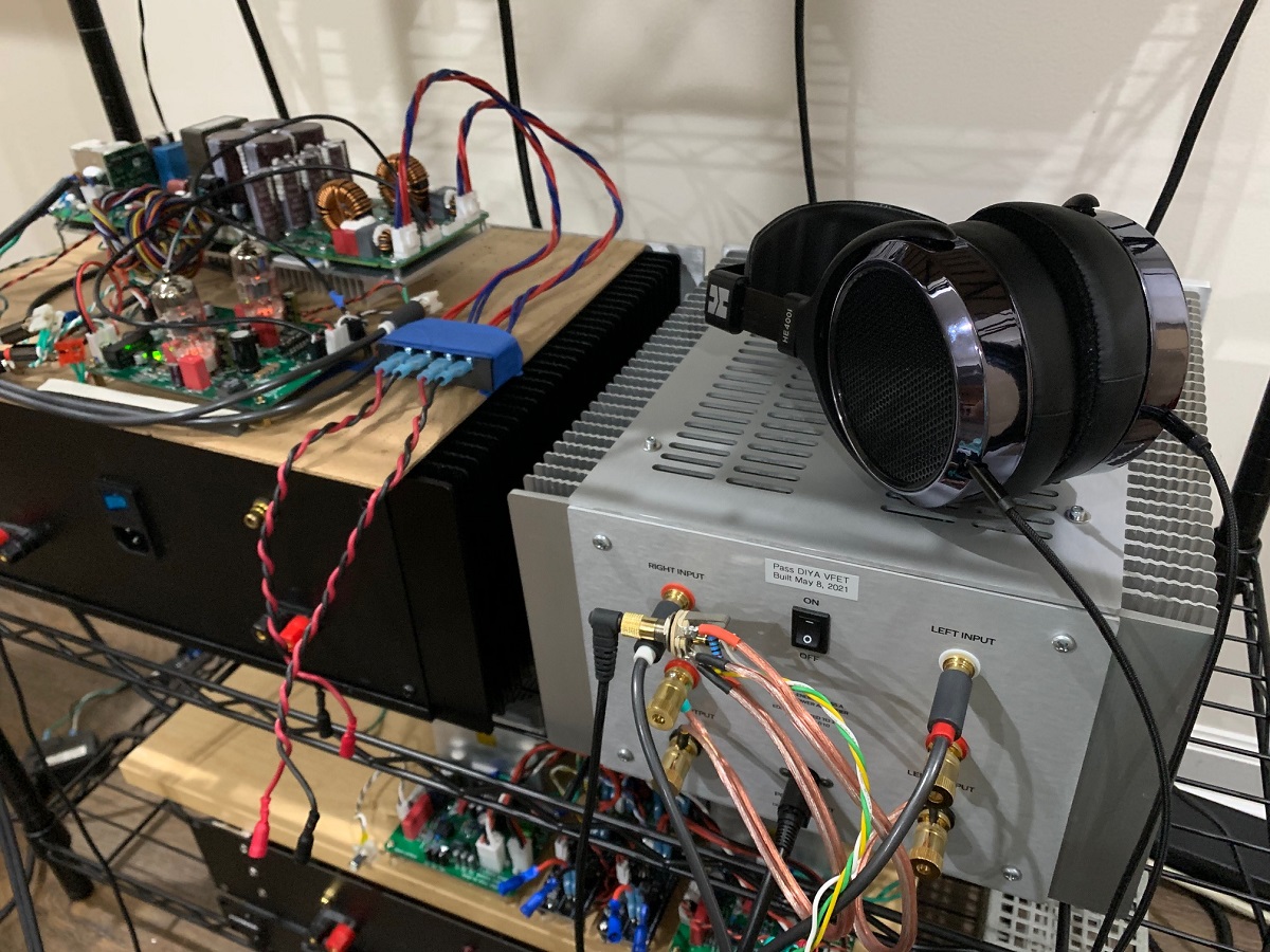
The VFET drives HE-400i planars very nicely.
It’s quite a nice headphone amp, even direct drive - no transformer needed. It’s quiet enough to be a headphone amp that’s for sure. You might have missed this:
DIY Sony VFET Builders thread
The VFET drives HE-400i planars very nicely.
This question is more directed to Mark Johnson, if not too much asking... (but of course any opinion is more than welcome!)
I understand a new 6A SMPS filter is under evaluation and may be released... or not. a 4th order one, with so far an unknown Fc.
Now, I still have many of the PO98ZB filters here with me, great little boxes. I do understand these are not rated for the VFET, being max 3A only (albeit 48V). These 4th order SMPS filters are very small and easy to integrate... and one channel of the VFET draws around 1.6A under 36V. There are already two "+V" two "G" outputs in the existing VFET filter, one for each OS channel...
Now to the questions:
- is there any problem running two PO89ZB filters, one between each OS board feed and the already existing VFET filter, so that each PO89ZB only sees less than 2A before feeding the OS board? Is this a problem "somehow" to parallel these units in such a manner?
- Is there any downside doing so regarding sound or else?
As all the Grounds are connected anyway, I had in mind to keep feeding the "G" to the FE boards directly per the existing original filter, which apart from some parasitic cable resistance should hopefully not be a problem (?)
This could be an experiment while waiting for the possible release of the 6A filter, If it happens. Of course, the VFET being precious, I rather ask the designer first hand if this is an intersting idea or just one of my late eve deliriums🙂
Mark, I would greatly appreciate your view on this idea before looking deeper at the physical implementation feasability...
Many thanks as ever
Claude
Dreadnought Boards
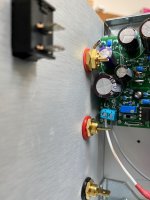
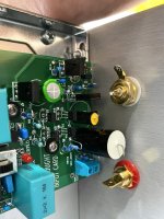
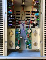
First a few notes on fitment.
I chose the horizontal configuration, as installing the boards vertically looked like they wouldn't fit. I also had the original boards mounted horizontally, so I was somewhat predisposed to that. Now, after finally shoehorning the boards in place, I think they could also fit vertically, perhaps just with different issues. The horizontal orientation imposes some component size restrictions, and I ended up making some changes after it became apparent that there would be interference. Other builders may prefer the vertical orientation. Some pics may help decide.
Initial listening impressions are good so far. As expected, the stereo separation and imaging are quite good. For maybe a little less effort than building an external linear PSU, these boards are another way of bringing the benefits of dual-mono power to the front end. I expect all of the new front end cards announced so far to provide these benefits, so they are probably worth trying for that at least. The question is whether to include the Edcor iron in the signal chain, or maybe high voltage opamps. Several choices.
What I have heard so far suggests that the Dreadnought boards present a soundstage that is slightly less forward in character than the original. Regardless, it fills my listening space very well. Bass is deep and articulate. Those who may worry about using a 2.7 uF film cap on the output may rest easy, as that will be a fine choice for supporting the bottom octave of bandwidth. I enjoy performances that feature good bass players, and this amp as proven to be quite satisfying in that area.
I will wait until the new boards have a few more hours on them before commenting further, but I like them so far.
Attachments
Soundhappy, wonderful to hear how you're enjoying your well deserved SE Sony Vfet amp build! I'm hoping to get lucky in the next lottery but if not I have several superb non DIY SIT amps that I've been enjoying Tears for Fear on.This song of the band Tears for Fears is not easy to reproduce on the audio system.
The $10 SMPS filter kits in the diyAudio Store, use an LCLC circuit topology. As long as you don't deviate from the recommend part numbers, and as long as you don't apply a voltage greater than 48V DC, AND as long as you don't draw more than 3 amperes through the board, it will work fine. How you use it in your project(s), is completely your decision. You'll probably decide to perform a few different experiments and see which arrangement gives the results you like best.
I happen to think there is a high probability that the next batch of VFET amplifiers (the ones with Nchannel VFETs) will ship with a new and different SMPS filter board, than the filter board shipped with the first batch (the ones with Pchannel VFETs). So I plan to sit and do nothing and wait until those amps are shipped and those SMPS filter boards are unveiled. And then, see whether I can figure out a way to be compatible with the new filter board. Perhaps, if very lucky, compatible with BOTH the first SMPS filter board AND the new SPMS filter board. But that's just wishful thinking.
_
There were rumblings from The Man that the new SMPS filter boards will incorporate a delayed turn-on feature. We shall see.
Many thanks for your kind reply, Mark!
I understand the vaillant PO89ZB has only 2.2uF coils vs 56uF ones on the pix of the board that is under development (couldn't see the caps values and deduce Fc), and that the latter is probably much more performant re filtering and for sure dedicated for that use, but at least thanks to your reply I feel more confident to... experiment with what I have available. For now 🙂
Fingers X for the future and thanks for all these developments and the time you take to reply individualy, whatever the outcome for the first batch VFETs
Claude
There is indeed a different power supply filter for the n channel version which does more filtering in exchange for slight voltage loss, this because the cmrr of the circuit is not as high. Also a relay for thump suppression as this version has a larger turn on / turn off transient. Actual performance is otherwise virtually identical.
Thanks for kind words..Soundhappy, wonderful to hear how you're enjoying your well deserved SE Sony Vfet amp build! I'm hoping to get lucky in the next lottery but if not I have several superb non DIY SIT amps that I've been enjoying Tears for Fear on.
is my friend who enjoy now play nice music with SE Vfet amp 🙂
If not luck in the winn a lottery kit then buy quickly big Tokin triodes is a solution.
😉 Stock availability goes low..
First a few notes on fitment.
I chose the horizontal configuration, as installing the boards vertically looked like they wouldn't fit. I also had the original boards mounted horizontally, so I was somewhat predisposed to that. Now, after finally shoehorning the boards in place, I think they could also fit vertically, perhaps just with different issues. The horizontal orientation imposes some component size restrictions, and I ended up making some changes after it became apparent that there would be interference. Other builders may prefer the vertical orientation. Some pics may help decide.
Initial listening impressions are good so far. As expected, the stereo separation and imaging are quite good. For maybe a little less effort than building an external linear PSU, these boards are another way of bringing the benefits of dual-mono power to the front end. I expect all of the new front end cards announced so far to provide these benefits, so they are probably worth trying for that at least. The question is whether to include the Edcor iron in the signal chain, or maybe high voltage opamps. Several choices.
What I have heard so far suggests that the Dreadnought boards present a soundstage that is slightly less forward in character than the original. Regardless, it fills my listening space very well. Bass is deep and articulate. Those who may worry about using a 2.7 uF film cap on the output may rest easy, as that will be a fine choice for supporting the bottom octave of bandwidth. I enjoy performances that feature good bass players, and this amp as proven to be quite satisfying in that area.
I will wait until the new boards have a few more hours on them before commenting further, but I like them so far.
I went with a vertical placement. Only recommendation would be to use 15mm or more standoffs
Pass DIY Addict
Joined 2000
Paid Member
SOME THINKING RE SMPS FILTERING for the VFET amp
(sorry, quite long, skip if boring 🙂
The filter that comes with the VFET kit is a 2nd order filter with Fc = 460Hz. Quite nice.
The SMPS that comes with the VFET is not very well documented regarding output ripple and noise, nor what output filter it has built inside already at its output, so it would be handy at least to plug a (good) scope and measure what comes out. Enters Mark Johnson, who elsewhere pointed to the existence of Meanwell test reports, and although we don’t get the figures in written we can find on those…some nice oscilloscope captures regarding ripple and noise. Handy. It appears that this SMPS seems to produce some LF ripple and noise (at twice the main’s frequency probably) and some HF ripple and noise, that seems to have its main component at a tad under 200kHz - and some much higher frequency components with a very low amplitude - presumably related to the intrinsec operating frequency of the SMPS. I chose to focus on LF = say 100Hz ish, and HF = say 200kHz.
Let’s see how to tackle both. I know some will argue that the 200kHz ripple and noise are well outside the audio band, but IME they do impact audio a way or an other. And I trust my ears on that, more than any of my diplomas, privilege of what came first LOL.
The LF can’t really be addressed easily unless you build a filter with a very very low Fc. Could be done, but in our application « may » have some downsides re dimensions/integration or voltage losses and cost. On the other hand, I am not sure it would get me anywhere as the addition of large output capacitors could exactly address this in a possibly suffisant manner. I don’t know how the existing SMPS filter addresses this already, but it probably does to some extend due to its 1000uf output cap. Anyway, my idea is to add one 1500uF cap betwen +V and G on each OS board, feeding the OS board (and, as ever, the related FE board). That should help the LF ripple, should it be needed. And the HF ripple as we shall see.
The HF ripple is indeed somewhat addressed by these additional caps. Depending on how you model it, you can (simplifying a lot) either consider that the existing 2nd order filter has now Fc = 230Hz. Or you can consider that due to the extra cabling, you have added for each channel a RC 1st order filter after the existing filter. Taking 0.02R as the cable resistance (pure guess work), that second filter would have Fc = 5kHz. I like that model, shows some better channel separation and the resulting filter is the sum of 2 filters, so you just add slopes on a bode diagram where appropriate, albeit I am not sure that at 200kHz the 1500uF caps are still at their best. In real life, the filter has a less schematic response (starting of course earlier than Fc, more rounded off around Fc, and ultimately it has a finite filtering response capability – I don’t really know what to think of figures below -60dB in my DIY filtering works), or perhaps even worst a downgraded response at very HF. But anyway, as far as we are concerned, we get already a reasonable filtering job done at 200kHz anyway, be it thanks to Papa’s filter.
Nevertheless, we could go further and try different things. The VFET can tolerate some marginal voltage feed losses, so why not adding a low DC resistance SMPS filter that has a solid pedigree and that trully worked well even in optimised set ups ? One that is made for that, one that has been designed by someone skilled who probably took a lot of time to hone it: Mark’s PO89ZB. I have a dozen of these and they are amazing SMPS filters. They are also non expensive and with a small form factor, handy for integration. Problem is they are designed for up to 3A and 48V, and probably work trully well when quite within their current limit. Sadly, the VFET amp draws a bit more than 3A, but then one channel only… 1.6A. Hence putting one of these filters betwen the existing filter board (that I consider really as a remote final part of the existing SMPS) and each OS board feed (right before « my » additional 1500uF caps). Problem solved, and we get now an additional 4th order filter with Fc = 5kHz… and negligeable voltage losses regarding the PS (may perhaps check the bias in case it needs a marginal touch of adjustment, just in case ?).
As a side note, the B1 Korg has in my case (later caps increase) as main feed a very good 2nd order RCRC filter with Fc = 7Hz (!) - and yet it still benefitted from the PO89ZB filter, possibly due to very HF content…
Regarding HF filtering, I see « my » entire chain taken from the output of the SMPS as :
- a standart 2nd order filter with Fc = 460Hz (and HF filtering capable)
- a channel feed separation
- a 4th order filter with Fc = 5kHz (and very HF filtering capable)
- a 1st order filter with say Fc= 5kHz (and barely HF filtering capable, just a bonus from our LF work)
Or perhaps (neglecting the filter’s output cables) as :
- a standart 2nd order filter with Fc = 460Hz (and HF filtering capable)
- a channel feed separation
- a 2nd order filter with Fc = 5kHz (and very HF filtering capable)
- a 2nd order filter with Fc= 2.4kHz (and very HF filtering capable)
Whatever, quite something promising to… try, of course, as only the sonic result matters.
Regarding LF, we get of course all this aswell but given the various Fc we are considering, we can IMHO safely ignore the filtering capabilties for LF. Nevertheless, we have added quite some extra capacity to help the LF ripple. If we consider only this very limited section of the amp, we moved from 1000uF for both channels to the said 1000uF for both channels with the addition of 2x 470uF + 1500uF = 2440uF per channel. Some additional R in the line indeed, but lower ESR cap at the end in direct feed anyway. That should help quite a bit LF ripple and noise, should it ever be needed and LF response aswell hopefully. So from 1000uF to 5880uF in total for the entire VFET amp.
As a side note, I have seen in Class D amps similar SMPS firing up without any problem - and without « benefitting » from many time constants due to Ls and Rs ‘in the way’- with 6000uF of PS caps and even over 9000uF, so the SMPS hiccup safety should hopefully not trigger… Fingers X.
Let’s see if in real life all that makes sense or… changes nothing or even ends up being worst LOL !
Nest step is the addition of the two 1500uF caps on the OS boards, probably followed by the installation of the 2 SMPS filters.
Claude
Sounds like a plan 
I found that the current draw of my VFET amp is about 1.7A per channel, or slightly higher. If you use SMPS filters rated for 3A, then you will need a separate one for each channel. We also have an existence proof that RCRC filters work in the alternate front end boards designed by Mark J. Those boards use 16 Ohms and 470 uF. That resistance to too high for the whole amp, but works well for small front end circuits. If you have the mind to experiment, you might try separate RC filters for the front end, and different networks for the output stages.
I found that the current draw of my VFET amp is about 1.7A per channel, or slightly higher. If you use SMPS filters rated for 3A, then you will need a separate one for each channel. We also have an existence proof that RCRC filters work in the alternate front end boards designed by Mark J. Those boards use 16 Ohms and 470 uF. That resistance to too high for the whole amp, but works well for small front end circuits. If you have the mind to experiment, you might try separate RC filters for the front end, and different networks for the output stages.
Last edited:
Hi TungstenAudio,
Thanks for your kind encouragements 🙂
Yep, as posted, exactly for that very reason (current draw) I intend to use 2 SMPS filters: one in front of each OS board, following the existing filter board. Well within the 3A then... sorry if my long text was confusing.
Regarding the extra filtering for the FE board, you are opening an interesting new idea. I must confess so far I am first interested in evaluating the sonic impact of these FE boards alone by installing my 4PDT switch to enable taking the entire FE boards "in" and "out" (= sound of OS directly) by the flick of a switch (LOL). I can live in that system with 14dB less gain in the chain most of the time. But depending on the sonic impact of the FE boards, indeed adding just an additional RCRC would be a piece of cake given my existing PS and signal connectors and non expensive... hmm... I would have yet to look into the schematic to see how much R would be suitable to still feed the existing FE boards correctly in terms of voltage. Any idea?
Thanks for this idea TungstenAudio
Having said all that the VFET amp sounds absolutemy fantastic as is!!! Whaou! OK, in a perfect world I would maybe concentrate my very personal tweaks to slightly tune it for my ears and the Klipsch towards more slam & speed. This is DIYA after all, but we are talking minor bits, the basic is sooo enjoyable after now nearly 100h...
Enjoy music
Claude
Yes, I have found that the VFET amp retains a special character, or 'sound', even when swapping in a different front end. Smoothness and liquidity, similar to my old Dynaco ST-70, but with improved bandwidth and transparency.
- Home
- Amplifiers
- Pass Labs
- DIY Sony VFET Builders thread