Indeed very tight fit! Would be interesting to know how they fit vertically. That purple cap is dangerously close to the RCA connector for my peace of mind / OCD.First a few notes on fitment.
I chose the horizontal configuration, as installing the boards vertically looked like they wouldn't fit. I also had the original boards mounted horizontally, so I was somewhat predisposed to that. Now, after finally shoehorning the boards in place, I think they could also fit vertically, perhaps just with different issues. The horizontal orientation imposes some component size restrictions, and I ended up making some changes after it became apparent that there would be interference...
Rafa.
^ The angle of that photo makes the purple cap look closer than it is. Besides, the boards aren’t going to move once they are screwed in. 😉
I must say I love the way this amp manages to sound so rich while having so many details in a huge soundstage. I could easily live with it as is, it makes horns sounding close to panels, amazing! Having said that, adding a little bit of personal spice to get a tad more "rapid rising fronts / slam" without ruining the above would be great.
Another bad habit from me when I fall in love with a unit, is to keep it forever and to like enhencing the existing as much as I can - tweaking it while keeping it as original as possible... strange challenge, but that's me.
That's why I like the idea of a FE bypass switch and also the one around a possible CRCRCR filter in front of the FE boards. A quick head guess make me believe that a single FE board could possibly draw 0.05A or so. Question: is that in the right ball park?
What I don't know is how would the existing FE boards react if I reduce the input voltage from 36V to say 31V. That is the equivalent of a RCRCRC filter with R=33 for 0.05A draw. My guess would be that everything should be OK, especialy given there is a 1k R to limit voltage anyway at the feed, except perhaps for less headroom, if wanting to extract a lot of Volts at the output, which I don't intend anyway, but my understanding of the circuit is far too limited to confirm this. It could also be that the following FET stage is tuned around a given voltage re sound... Anyone?
Many thanks
Claude
Last edited:
Why don't you wait and see what sized "slight voltage loss" you get, when you connect up the board of post #1613 ?
Was even too pessimistic, a longer glance while back from work gives me that each FE board draws less than 0.02A... 🙂
On the other hand the RC filter at the FE input is quite an efficient one already, despite being 1st order, it has Fc = 0.16Hz!
Gives roughly -27dB @ 90Hz, so same ball park as some RCRCRC on other FEs.
Not sure much more can be done re LF, it has been taken care of IMHO. Not necessarly for the HF though, although there is the filter board for the entire amp for that, but IMHO still worth trying the 1500uF additional caps for OS (and hence FE) for LF ripple etc. and the addition of 2 of Mark's SMPS filters in front of OS (and hence also filtering FE if keeping the genuine connections between boards) for HF.
Was worth the effort digging into all this once back, thanks!
Claude
Last edited:
You guys are over my head lol. im just thinking that mine is running just a bit hot....it is 58c on the aluminum bracket to the heat-sink. And 54C on the fins side.
I want to buy some test equipment and get deep into more building and checking and tweaking like you guys. looking at a few things any one got time for a phone call?
That amp does seem to be running a little hot. You should be able to keep your hands on the heat sinks indefinitely without discomfort. Make sure that you installed the mounting screws with extra washers so that the screws don’t bottom out before the T brackets are in firm contact with the heatsink.
Wouldn't the heat sink be cooler if the t bracket to sink thermal. resistance was higher than normal as it would be with loose screws.It sounds like really good thermal contact instead.I would check the bias.Others have said the vfet case is around 70 to 75 Celsius as normal.
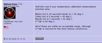
The heat is initiated at the device, so it's the hottest, it conducts to the bracket, (which has no large radiating surface and is inside the box) so it's the second hottest, only when the heat gets to the outside (the fins) is there a large radiating surface area to loose the heat to the air. Thus it's the coolest. The connections between these components are thermal barriers to a degree as you said but the relatively small temp delta tends to infer a reasonable connection. Has Mr Pass not said that the acceptable 55C on a heatsink allows a 10 second average touch time?
Last edited:
Has Mr Pass not said that the acceptable 55C on a heatsink allows a 10 second average touch time?
No. See link below.
https://www.diyaudio.com/forums/pass-labs/3748-aleph-186.html#post116146

As long as we are talking heatsinks..... Smaat Fella that I am.... Couldn't bring myself to purchase yet another 5U Delux case/parts kit for $600ish...... So I have endeavored to start procuring various Aluminum channels / plates / heatsinks / etc from the Bay.
Well.... I'm at the $200 mark already....let's see if I cob my way past the $600 mark....hehe.
Any bets on it actually being a better choice in the end ?
Well.... I'm at the $200 mark already....let's see if I cob my way past the $600 mark....hehe.
Any bets on it actually being a better choice in the end ?
Ok my little key-chain temp-meter is giving me some really wacky numbers. Just got a 137c # and i just don't believe that. um going to buy a new one tomorrow.
really depending what and where you need measurements, but for most basic ones, your Mom already gave you one
two, in fact
🙂
two, in fact
🙂
Hot or Not
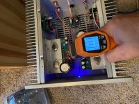
OK Klein infrared thermometer. Emissivity set to .80 and amp warm up for 1hour 30 mins. No load just on. I will check the bias again and in an hour or so
OK Klein infrared thermometer. Emissivity set to .80 and amp warm up for 1hour 30 mins. No load just on. I will check the bias again and in an hour or so
Attachments

Last edited:
- Home
- Amplifiers
- Pass Labs
- DIY Sony VFET Builders thread