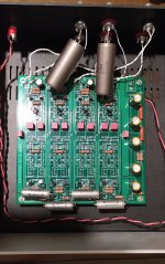
Finally put mine together! Working well so far. Really appreciate the unity gain factor - given it's paired with a TVC preamp, it just slots right in - no need to adjust levels.
I was wondering what's everyone using for a power supply? I'm currently using a 24v wall wart, but I saw a few images of beefier PSUs too - was curious about them ...
And please ignore the DC cable run - i didn't want the cables running over, or in proximity to the input cables and caps.
I was wondering what's everyone using for a power supply? I'm currently using a 24v wall wart, but I saw a few images of beefier PSUs too - was curious about them ...
And please ignore the DC cable run - i didn't want the cables running over, or in proximity to the input cables and caps.
Attachments
Hello diyaudio, just received my boards and I’m compiling my order for this cool project, but need some help with selecting values for C1/C2. Really not sure how to use the Calculator provided. Maybe you could show me what and where I plug in my numbers.
So my crossover points are 70-280hz, 280-5khz, 5k-30khz
Right now I want to use my first board on the mids and tweeters.
Thank you in advance for your help. Ken
So my crossover points are 70-280hz, 280-5khz, 5k-30khz
Right now I want to use my first board on the mids and tweeters.
Thank you in advance for your help. Ken
Last edited:


I think it should be calculated this way:
12db: C(nf)=6000/Freq
6000/1200=5nf
6000/1600=3.75nf
6000/1800=330pf
18db: C(nf)=7000/Freq
7000/1200=5.83nf
7000/1600=4.38nf
7000/18000=389pf
If this is correct then, How would you calculate for 24db? Thanks Ken


Some photos of a 6-24 crossover built into a preamp
Hi Everyone,
I thought I'd share some photos of my build. It's actually my second; the first worked great, but I decided I wanted one built into a preamp. The plan is to use the other one eventually together with this one in a three-way XO.
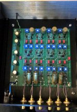
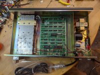
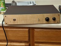
The enclosure came from Surplus Sales of Nebraska. Apparently some ancient computer equipment from the mid-1970s. Solid steel, built-in transformer and power supply; I thought it had to be worth gambling $16 (plus shipping). To my amazement it arrived in original styrofoam and box; never used and looks really nice. The first picture shows the insides before I dumped it all out. I had planned to keep the transformer, but I ended up switching out for another I had.
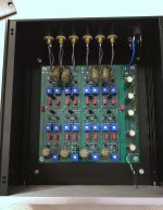
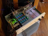
Second photo shows inside the case with the passive preamp, XO and new power supply installed. Supply is the schematic from Salas' L'Adapter thread, adjusted to give 24V output using a string of green leds and a 24VAC center-tapped transformer with two MUR810 diodes and a 2SA1943 I had kicking around. If I ever finishing the tri-amped system I intend to power the other XO from this same supply.
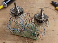
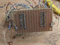
I also wanted to play with a diy stepped attenuator. At the risk of being a little off-topic I'm also including two photos of that. If I was doing it again I would work more carefully to keep shorter wires, somehow, although it may only make a difference in the way it looks. It's a dual mono, since I like having separate L and R volume and no balance. Time will show whether 23 steps is enough for that to work well.
If you think of doing something similar, don't make my mistake. If you have a 23-step rotary switch and 24 wires, you probably care less about the lowest-volume step than the full-volume step. I'm not doing all those wires again (I'll never use it full volume anyhow) but it would have been nice to get it right.
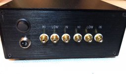
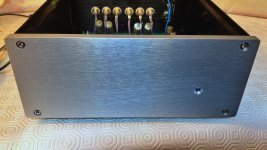
Finally, two photos of the finished article. I used a piece of curly maple for the front, which I'm pleased with. The knobs are just what I had handy to try it all out; I'd like some stainless steel ones to match the Schurter switch on the left (which is very nice, BTW) so if anyone has a suggestion of where to get them let me know.
I have it set up as the 24db/octave option, and used REW to set crossover point at about 2300Hz. I have diy F5s on tweeter duty, and my old Creek 5050 handling the woofers. Speakers are old Mission 700s sans passive crossovers. Sounds great.
I originally intended to make it modular, and to experiment with different gain stages, but now I'm listening to it I don't think it needs one. There's plenty of space to build in tweaks or more functionality though. I might try different input/output caps, although quite honestly it sounds good enough I'm in no hurry. Although I might have to get in there and tidy it up; other people's builds above look beautifully tidy: Lordvader, Decker, Peppenino; nice work! Makes me feel a little embarrassed at my sloppy wiring.
Nelson: thanks so much for all you do for us on this site, and for this project in particular. It's much appreciated.
Best
Nigel
Hi Everyone,
I thought I'd share some photos of my build. It's actually my second; the first worked great, but I decided I wanted one built into a preamp. The plan is to use the other one eventually together with this one in a three-way XO.
The enclosure came from Surplus Sales of Nebraska. Apparently some ancient computer equipment from the mid-1970s. Solid steel, built-in transformer and power supply; I thought it had to be worth gambling $16 (plus shipping). To my amazement it arrived in original styrofoam and box; never used and looks really nice. The first picture shows the insides before I dumped it all out. I had planned to keep the transformer, but I ended up switching out for another I had.
Second photo shows inside the case with the passive preamp, XO and new power supply installed. Supply is the schematic from Salas' L'Adapter thread, adjusted to give 24V output using a string of green leds and a 24VAC center-tapped transformer with two MUR810 diodes and a 2SA1943 I had kicking around. If I ever finishing the tri-amped system I intend to power the other XO from this same supply.
I also wanted to play with a diy stepped attenuator. At the risk of being a little off-topic I'm also including two photos of that. If I was doing it again I would work more carefully to keep shorter wires, somehow, although it may only make a difference in the way it looks. It's a dual mono, since I like having separate L and R volume and no balance. Time will show whether 23 steps is enough for that to work well.
If you think of doing something similar, don't make my mistake. If you have a 23-step rotary switch and 24 wires, you probably care less about the lowest-volume step than the full-volume step. I'm not doing all those wires again (I'll never use it full volume anyhow) but it would have been nice to get it right.
Finally, two photos of the finished article. I used a piece of curly maple for the front, which I'm pleased with. The knobs are just what I had handy to try it all out; I'd like some stainless steel ones to match the Schurter switch on the left (which is very nice, BTW) so if anyone has a suggestion of where to get them let me know.
I have it set up as the 24db/octave option, and used REW to set crossover point at about 2300Hz. I have diy F5s on tweeter duty, and my old Creek 5050 handling the woofers. Speakers are old Mission 700s sans passive crossovers. Sounds great.
I originally intended to make it modular, and to experiment with different gain stages, but now I'm listening to it I don't think it needs one. There's plenty of space to build in tweaks or more functionality though. I might try different input/output caps, although quite honestly it sounds good enough I'm in no hurry. Although I might have to get in there and tidy it up; other people's builds above look beautifully tidy: Lordvader, Decker, Peppenino; nice work! Makes me feel a little embarrassed at my sloppy wiring.
Nelson: thanks so much for all you do for us on this site, and for this project in particular. It's much appreciated.
Best
Nigel
Attachments
Last edited:
I'd like to use the 6-24 with my two-way infinite baffle speakers; I will measure their response, and curves are available for the drivers. I know where the crossover point is.
I'd like to start with a 24-db Bessel function, with the aim of reducing phase shifts particularly around the crossover region.
@mallikreddyk suggests VituixCAD. Any other suggestions or tips on how to implement this?
In particular, how to turn the transfer function into component values. I've read the briefing notes but I'm not an electronics engineer...
Looking for 6-24 'Builder'
signalbeach: I too like te idea of 'fixed' resistors (as opposed to multiple 'pots') as you describe here.
For me, the 6-24 will be used as a simple, fixed frequency subwoofer/main x-over: 45 Hz. crossover point (24 db/octave LR).
If there is anyone here at DIY who can do the build ( I have all the parts, including chassis, connectors, WBT solder and both LPS and SMPTS power supplies), please contact me.
Forgive me, I'm a newbie, so am not sure where I should be posting this ?
Thank you.
pete
In the 24 db/octave crossover section of the 6-24 documentation it says:
"The only point to note is that the classic L-R alignment will result from the P2 potentiometers to be at around 1/2 the resistance of the other pots" To clarify, this ONLY applies to P2 pots of the High Pass sections.
Given the number of pots to adjust, it might be easier to use an inexpensive crossover or miniDSP to predetermine your crossover points. I used a dbx 223xs.
Then, you can calculate the needed R values using an online calculator or program. I used this one for Windows found at Elliott Sound Products: https://sound-au.com/software/esp-lr13.exe
With the R values in hand, you can then preset the pots or just use fixed resistors. Since I don't like having 16 pots in circuit, I'm planning to use fixed resistors.
Thanks Nelson for another great project !
signalbeach: I too like te idea of 'fixed' resistors (as opposed to multiple 'pots') as you describe here.
For me, the 6-24 will be used as a simple, fixed frequency subwoofer/main x-over: 45 Hz. crossover point (24 db/octave LR).
If there is anyone here at DIY who can do the build ( I have all the parts, including chassis, connectors, WBT solder and both LPS and SMPTS power supplies), please contact me.
Forgive me, I'm a newbie, so am not sure where I should be posting this ?
Thank you.
pete
Thank you
Hi Al: Thanks for the prompt reply. SAnd sorry abpout my late reply.
Great question: The chassis at this point is not drilled for the connectors, although that can be done prior to shipping it.
I don't know if PM's (personal messages) can be sent, or iof I can provide my email address, but if I can do so it is: mrpjaszATgmaildotcom
Thank you kindly.
pete
I've got a couple of questions about setting the potentiometers on the 6-24. I have been playing with the doublesecretlabs crossover calculator to make a table of values for crossover slopes and frequencies that I want to try. The calculator refers to R1, R2, R3 and R4 for values. How do R1, R2, R3 and R4 relate to P1 and P2 for the first stage and P1 and P2 of the second stage on the board? And where are the test points on the board that I should be measuring to set the correct values? With the board mounted in the chassis, I can't get at the bottom of the board to measure the pots directly. To which resistors and which end of said resistors should I attach the test leads of my DVM? Thanks.
Tri-amp with subwoofer
Hi all,
Using two boards: If I set the XO of board 1 to say 100hz, and feed the sub off the LP output. Then feed the HP output of board 1 to board 2. The HP signal of board 1 fed to the second board would create a bandpass for the for the LP output of board 2, correct?
Hi all,
Using two boards: If I set the XO of board 1 to say 100hz, and feed the sub off the LP output. Then feed the HP output of board 1 to board 2. The HP signal of board 1 fed to the second board would create a bandpass for the for the LP output of board 2, correct?
I've got a couple of questions about setting the potentiometers on the 6-24. I have been playing with the doublesecretlabs crossover calculator to make a table of values for crossover slopes and frequencies that I want to try. The calculator refers to R1, R2, R3 and R4 for values. How do R1, R2, R3 and R4 relate to P1 and P2 for the first stage and P1 and P2 of the second stage on the board? And where are the test points on the board that I should be measuring to set the correct values? With the board mounted in the chassis, I can't get at the bottom of the board to measure the pots directly. To which resistors and which end of said resistors should I attach the test leads of my DVM? Thanks.
There are no dedicated test points. The 10k series resisters are directly above and below the pots so that gives you one end of each pot. For high pass there's a plated through hole next to P1 and for P2 you can use one end of the bias resister. For lo pass I used the caps but if you can't get under them you can use resisters leads too as you can see in the schematic.
Also note that the calculator R1 to R4 are the sum of the pot resistance and 10k resistor.I've got a couple of questions about setting the potentiometers on the 6-24. I have been playing with the doublesecretlabs crossover calculator to make a table of values for crossover slopes and frequencies that I want to try. The calculator refers to R1, R2, R3 and R4 for values. How do R1, R2, R3 and R4 relate to P1 and P2 for the first stage and P1 and P2 of the second stage on the board? And where are the test points on the board that I should be measuring to set the correct values? With the board mounted in the chassis, I can't get at the bottom of the board to measure the pots directly. To which resistors and which end of said resistors should I attach the test leads of my DVM? Thanks.
to TboneAK #637
Hello TboneAK,
I have built a linear regulated powersupply:
Transformer - rectifier- CRC-filter- adjustable voltage regulator (lm317 or LT1084/1085).
I have built many. The pcbs have been bought on E--y and from a german
hifi-freak offering pcbs.
But you can find them also in the states. This is a very 'classic' PSU with adjustable voltage output.
Greets
Dirk
- Home
- Amplifiers
- Pass Labs
- DIY biamp 6-24 crossover