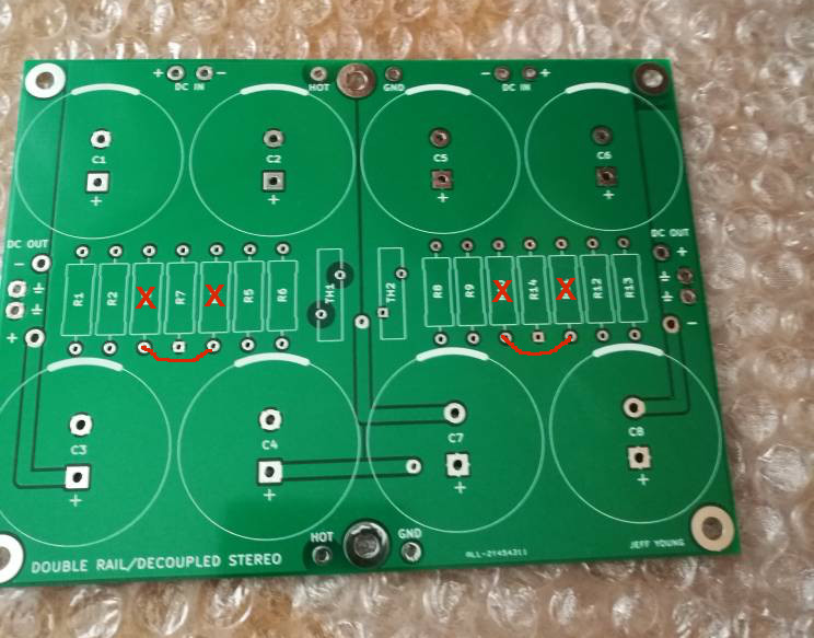
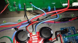
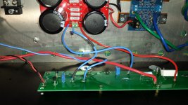
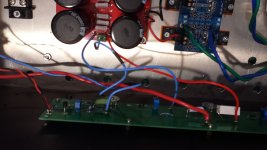
R7 and R14 bleed-off resistors?
Correct.
Thanks! So, I want to stress the importance of following the schematic when populating the PCB.
This board isn't like the store's board where you can drop in the CRC resistors.
The bleeder resistors physically break up the CRC resistor array.
I'm saying this because I already installed them incorrectly and only notice this today.
So thanks Jeff for clearing that up!
Vince
This board isn't like the store's board where you can drop in the CRC resistors.
The bleeder resistors physically break up the CRC resistor array.
I'm saying this because I already installed them incorrectly and only notice this today.
So thanks Jeff for clearing that up!
Vince
Thanks once again for your generousity Jeff (we spell it with a 'U' in Canada)!
Gerber View of PSU
I unpacked the zip and extracted the files with a PSU in them and rezipped them. The packed PSU files seems to generate a proper gerber based on the viewer above.
I didn't read the thread to see if there is an accompanying schematic so don't know if one exists. I do see what look like 3 spots for CL-60/thermistor but not sure.
Thank Jeff, not me
Thanks Jeff!
Attachments
@twitchie, that's the one before I fixed the spacing. I just replaced the .zip in the F3 thread with the one with larger spacing -- so you'll need to re-do your .zip. Sorry 'bout that....
(For some reason the silkscreen labels didn't come through on your Gerbers. Let me know if the next set don't show them either and we'll figure out what's going wrong.)
And you're right, I don't appear to have ever done a schematic for that one.
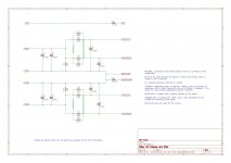
TH-1 is the surge suppressor on the "hot" line, TH-2 is a ground lift from left 0-volts to chassis ground, and TH-3 is a ground lift from right 0-volts to chassis ground.
There are 2 connection points for chassis ground next to the middle mounting holes: I use one for the chassis connection and one for the transformer shielding ground.
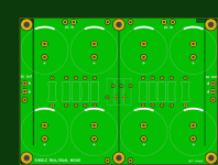
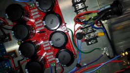
R1-R4 and R6-R9 are 0R47 3W; R5 and R10 are the 2K2 bleeders.
Capacitors are 10mm pitch snap-ins with a max diameter of 35mm.
(For some reason the silkscreen labels didn't come through on your Gerbers. Let me know if the next set don't show them either and we'll figure out what's going wrong.)
And you're right, I don't appear to have ever done a schematic for that one.
TH-1 is the surge suppressor on the "hot" line, TH-2 is a ground lift from left 0-volts to chassis ground, and TH-3 is a ground lift from right 0-volts to chassis ground.
There are 2 connection points for chassis ground next to the middle mounting holes: I use one for the chassis connection and one for the transformer shielding ground.
R1-R4 and R6-R9 are 0R47 3W; R5 and R10 are the 2K2 bleeders.
Capacitors are 10mm pitch snap-ins with a max diameter of 35mm.
I figured out the silkscreen issue in @twitchie 's Gerbers: the naming convention changed from "F.Silk.gbr" to "F_Silk.gbr" somewhere between KiCad 4.0.7 and 5.1, so the .zip has both sets (and one is wrong).
I've uploaded a new, cleaned up .zip to the F3 thread: F3 Builders Thread. Sorry for the run-around....
I've uploaded a new, cleaned up .zip to the F3 thread: F3 Builders Thread. Sorry for the run-around....
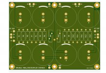
Indeed, this board is designed to need only one.
However, if you did want to use two, you can:
1) delete R3, R4, R10 and R11
2) change R1, R2, R5, R6, R8, R9, R12 and R13 from 0R33 to 0R47
3) solder a jumper between the lower holes of R3 and R4, and one between the lower holes of R7 and R8
Use as large a wire as you can fit for the jumpers.
Cheers,
Jeff.
I did changes on your original schematic. Now it's look like this. Can you check becouse I'm afraid it isn't right
Attachments
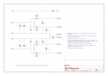

Not working. Getting voltage irregularities.
Either r7 and r14 are mandatory or the ground is wrong. I have the circuit ground going to the audio ground. Is audio ground 0 volts, center tap?
Either r7 and r14 are mandatory or the ground is wrong. I have the circuit ground going to the audio ground. Is audio ground 0 volts, center tap?
Attachments
Last edited:
Yes, don't use jumpers for R7 and R14 it will be direct to ground as you stated.
PSU Schematic - back from Post #15
I see you put a CL60 in the ground connection. Center tap should be 0V. You should be able to stick any suitable resistor in the bleeder position but it shouldn't affect operation.
What kind of irregularity are you seeing? Does it measure proper and steady not connected to the amp channels?
Last edited:
- Home
- Amplifiers
- Pass Labs
- Alternate First Watt Power Supply Schematic