This one fits that bill, or the store one.
While it could be done using this board, omitting R7 and R14 then bridging the two outs for A and B channels.
I still prefer a version with 8 caps per channel instead of 4.
That is what I was searching for.
-Michael
I dont think that counts as typical. Being a F5 Turbo PSU it is quite a bit beefier than standard firstwatt PSUs. I am not aware of a board for that, but since it isnt the number of caps but the total capacitance that matters you should be able to get around it. Putting 8 caps per rail could also present some difficulties space-wise in a typical chassis.
Are Gerber files checked and good for production?
At least one set of boards has been made from them already. See post #29 for pictures of mine being tested.
(Note: it was a small run and all of them have already been spoken for. I used EuroCircuits for what it's worth.)
Cheers,
Jeff.
While it could be done using this board, omitting R7 and R14 then bridging the two outs for A and B channels.
I still prefer a version with 8 caps per channel instead of 4.
That is what I was searching for.
-Michael
You could use a pair of my single rail / dual mono boards, but you'd need either two transformers or one with 4 secondaries.
If interested you can find the Kicad files (and Gerbers) in my F3 project files: F3 Builders Thread
Cheers,
Jeff.
You could use a pair of my single rail / dual mono boards, but you'd need either two transformers or one with 4 secondaries.
If interested you can find the Kicad files (and Gerbers) in my F3 project files: F3 Builders Thread
Cheers,
Jeff.
Thanks Jeff. I will investigate that.
Just for the record, your board design is excellent.
Regards,
Michael
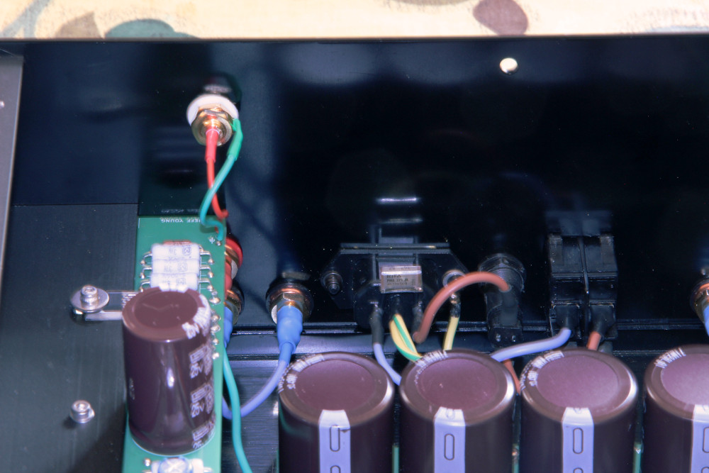
BTW, if anyone happens to notice the rectifier/snubber board on the front of the case in my test pictures,
Would snubbers provide additional benefit to this particular IXYS VBE 60-06A Bridge Rectifier that states as an advantage "Soft reverse recovery for low EMI/RFI"? Presumably, this particular device has minimal ringing.
Last edited:
Would snubbers provide additional benefit to this particular IXYS VBE 60-06A Bridge Rectifier that states as an advantage "Soft reverse recovery for low EMI/RFI"? Presumably, this particular device has minimal ringing.
After many years Nelson changed his mind about FREDs, which argues that there's something here that can be heard (and that it's not just expectation bias). But I don't think we know for sure that it's the ringing (or lack thereof).
FREDs do ring less, but they still ring. So does critically damping that ringing still produce a discernible difference, or did the FREDs already get us beyond what can be heard? I don't think we know that either.
But here's something I do know: It's cool to see the ringing on your oscilloscope and then critically damping it with a snubber. That's enough for me. 😉
Thank you. I read the Hagerman article. And various diyaudio threads. As I recall, I have read where Nelson Pass was kind of coy about it. I shall have a look at that particular bridge with a scope and go from there. I am mostly interested in low EMI. Thanks again.
Last edited:
Look for the Quasimodo thread at diyaudio, there is lot's of information and explanation.
Also, the creator of the Quasimodo wrote an article for linearaudio, and you can just buy and download the pdf there and be happy with all that information. I did it and it's better than all the articles I could find, including the ones you mentioned.
If I can hear it? I never tried and compared. But as Jeff mentioned: It's so nice to see the ringing on your scope, and see it go while you dial in the appropriate resistance to dampen it. For exactly this "Quasimodo style dampening", there are this 2 caps and 1 resistor in his board.
Have fun
Matthias
I’m looking to get a small batch of these made. Anyone in North America interested and I can get one (or more) in the order for you?
Right now I’m looking at using the posted gerber files. Should they be updated for 120VAC design with 2 thermistors on the board? I don’t have the knowledge or skills to update the files. Anyone interested in implementing that update?
Right now I’m looking at using the posted gerber files. Should they be updated for 120VAC design with 2 thermistors on the board? I don’t have the knowledge or skills to update the files. Anyone interested in implementing that update?
For a 110V implementation with two parallel transformer primaries I'd recommend doing the thermistors off-board as in 6L6's build guides. (The current board is based on a both a single thermistor and a single primary winding, which significantly reduces the number of connections required.)
6L6's method will also give you a location for the line suppression cap.
FWIW, with a single primary and the thermistor on the board, the easiest location for the line suppression cap is directly on the IEC inlet:
6L6's method will also give you a location for the line suppression cap.
FWIW, with a single primary and the thermistor on the board, the easiest location for the line suppression cap is directly on the IEC inlet:
Attachments

I honestly don't see anything with tightly twisted AC wires going from the back panel right to the front panel where the transformer is.
Would it be safer practice to put the suppression cap after the switch somewhere to avoid it being constantly subjected to line voltages?
It's also well documented that when certain RIFA line rated caps fail they short! I just learned about it myself from Dave Jones' video, but a google search shows incidents going back for years:
YouTube
I have a handful of these surplus RIFA caps and just be safe I tossed them.
It's better/safer to put any filtering after the fuse and switch in case of failure.
YouTube
I have a handful of these surplus RIFA caps and just be safe I tossed them.
It's better/safer to put any filtering after the fuse and switch in case of failure.
X1 and X2 capacitors are designed to fail short. That way they trip your circuit protection.
And yes, as I said above, in a 110V country I'd put them after the fuse and switch as in 6L6's build guides.
Here in Ireland (and in the UK) all plugs are fused, so I like them at the entry point to prevent any RF incursion into the chassis. YMMV.
And yes, as I said above, in a 110V country I'd put them after the fuse and switch as in 6L6's build guides.
Here in Ireland (and in the UK) all plugs are fused, so I like them at the entry point to prevent any RF incursion into the chassis. YMMV.
Update on the North America group buy. I ordered boards Friday. TBD on arrival date to me, I assume a couple weeks with fab and shipping from China. Boards should be 100% same as what you see earlier in this thread.
All but 3 boards are spoken for. PM me if you want one or more of the last 3. If I get a flood of requests, I'll boost the order size.
All but 3 boards are spoken for. PM me if you want one or more of the last 3. If I get a flood of requests, I'll boost the order size.
- Home
- Amplifiers
- Pass Labs
- Alternate First Watt Power Supply Schematic