As a semi retired elect engineer, one thing I have never done is mix AC mains voltage with low DC or AC voltages on any PCB, Even though Pass and others have done it in commercial designs, I would use this PCB as a CRC capacitance bank for a typical +/-25VDC power supply board only. I have some nice big fat 35mm dia snap in caps that I can use.
I am curious about this gary, as i've wondered about that part of the design myself from looking at the commercial FW supplies. What are the issues with putting AC on the same board here? I guess the main advantage is that it looks neat. Another nice thing about the FW supplies is that wires for the rails are taken from the sides of the board, rather than the end, which often is near the AC inlet if assembling the amp in the standard modushop case...
From my point of view, commercial designs have connections for incoming mains power wiring for several reasons - neat, saves time and cost, chassis space, drilling extra holes etc......
Provided the PCB is laid out with correct mains voltage clearances (120V or 240V) to all other lower voltage tracks then all is fine. Valve (tube) amps have this all the time if using PCB's for both AC and DC high voltage supplies.
When building amps myself either line stage or power amps, then as a matter of principle I do not run or mix low and high voltage wiring and because I do not have commercial decisions to worry about then I carefully select cable paths and run twisted pairs or shielded wiring where needed. They do not have to be separated very far apart, to have no affect on each other.
Hello Jeff, I believe there is a safety issue with your board if you intend to use mains on that PCB as is done in the FW commercial products There are regulations and you need to keep minimum distances between mains voltages and your secondary transformer voltages.... I believe it is about 5mm but am not sure. Be aware...
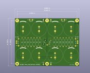
Hmmm... indeed. The board was designed with functional requirements rather than to meet UL certification. (From my reading of IEC60950 the "Functional" clearance for a 1,500V mains transient in a pollution class 2 environment is 0.56mm. The existing boards are 25mils/0.63mm.)
But I realise that might not make all interested folks happy, and UL certification is certainly a useful yardstick. From my reading of their requirements[1], a protective earthed pluggable consumer appliance should meet "Basic" insulation. With the same 1,500V mains transient / pollution class 2 environment that appears to net out at 2mm.
There's also "Reinforced" (which I believe is where the 5mm came from), but that's for "double-insulated" appliances with no protective earth.
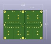
Anyway, I updated the design with 2mm clearance for the "hot" nets:
[1] https://composter.com.ua/documents/IEC60950-1.pdf
Attachments
Hi Jeff,
That revision should keep others happy, how did you go with loading the board with components and checking of DC voltages?
From looking at the PCB artwork - all seems fine with it to me.
Cheers,
Gary..
That revision should keep others happy, how did you go with loading the board with components and checking of DC voltages?
From looking at the PCB artwork - all seems fine with it to me.
Cheers,
Gary..
This is not my week for having my ducks in a row. The resistors labelled 3R3 on the schematic are supposed to be 0R33. (Which I fortunately noticed before soldering, but sadly not before I had ordered the wrong sized resistors.)
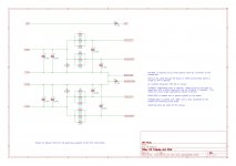
I noticed the values Jeff - these can be any value really between 0.1 ohm and 1.0 ohm, I use 0.47 ohm as I have stock of the Panasonic 3watt types. KOA Speer or Dale also have nice 2 or 3 watt resistors as well that could be used for these.
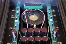
Some pictures of the board under test.
Top trace: transformer out; each little box on the screen is 10V.
Bottom trace: cap bank out; each little box is 10mV. It's still triggering on the 50Hz from channel one, so I believe what you're seeing here is essentially the noise floor of my setup.


The attached .zip archive contains the Kicad board file (much easier to send a single file if your board house accepts it), and the Gerbers (a bit more work).
(The schematic is in post #27.)
Let me know how you guys get on with it.
Cheers,
Jeff.
Top trace: transformer out; each little box on the screen is 10V.
Bottom trace: cap bank out; each little box is 10mV. It's still triggering on the 50Hz from channel one, so I believe what you're seeing here is essentially the noise floor of my setup.
The attached .zip archive contains the Kicad board file (much easier to send a single file if your board house accepts it), and the Gerbers (a bit more work).
(The schematic is in post #27.)
Let me know how you guys get on with it.
Cheers,
Jeff.
Attachments
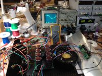


BTW, if anyone happens to notice the rectifier/snubber board on the front of the case in my test pictures, I posted the Gerbers for that over in the F3 thread: F3 Builders Thread.
Cheers,
Jeff.
Cheers,
Jeff.
Attachments
Hi Jeff, are you planing to make some small run for these boards or if you have some extras I would be interested 🙂
@PKI, I did a (very) small run but they're all already spoken for (2 sold and 1 reserved for Kumar).
It sounds like there's enough interest though for someone to organise another run. It might make more sense to do it from the States so everyone doesn't have to pay 21% VAT....
Cheers,
Jeff.
It sounds like there's enough interest though for someone to organise another run. It might make more sense to do it from the States so everyone doesn't have to pay 21% VAT....
Cheers,
Jeff.
Hello. Do I understand correctly: the entire hot line must be omitted if I have to build a device without grounding ?
Yes. (Or you need to increase the clearances on it.)
The easiest thing to do is to use a barrier strip to mount your thermistor.
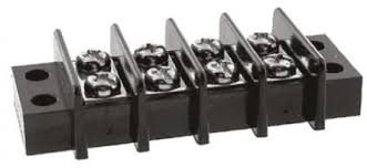
The easiest thing to do is to use a barrier strip to mount your thermistor.
Thanks. Maybe I will use a soft start instead of a thermistor. probably better in the case of installations without PE
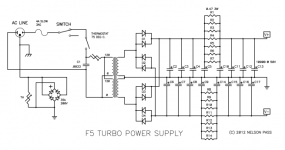
Has anyone created a board for the more typical First Watt style PSU?
Like this one:
https://www.diyaudio.com/forums/attachment.php?attachmentid=736131&stc=1&d=1550091604
Like this one:
https://www.diyaudio.com/forums/attachment.php?attachmentid=736131&stc=1&d=1550091604
Attachments
- Home
- Amplifiers
- Pass Labs
- Alternate First Watt Power Supply Schematic