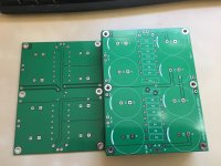
Boards are in - way faster turn around than expected. 4 left up for grabs. PM me if interested. I'll PM those who have some reserved to finalize details.
Attachments
Last edited:

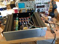
I received a few dual boards from different sources. Doing a repair on a simulated F7, so changing the store power supply board to this one. 🙂
Please post when you have it Fitted and had your first fire up impression.
After that.. imo.. subtle improvements no longer register in human brains.
After that.. imo.. subtle improvements no longer register in human brains.
After that.. imo.. subtle improvements no longer register in human brains.
Well, sound change might not be what some might be expecting, but some channel separation is better than none.
There could be a improvement in sound reproduction that some people are not even interested in, like sound stage improvements.
Tonally, there may be no change. 🙂
I have two simulated F7s, so it's easy for me to test. 😉
Hi Jeff, just placed order for these PSU boards and rectifier boards also. Thanks for sharing! Btw, where do you get those First Watt look-a-like cases? Would love to build one also.
that is a nice build - picked up 2 of these PCBs myself for a potential F5 V2 build ..dB

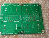
I want to use two pcb, each for one channel. What changes should I make?@darrr, wirewound are fine in this application (better, if anything).
This board is designed in such a way as to not need two boards. It's the exact purpose: one board for 2 channels.
Indeed, this board is designed to need only one.
However, if you did want to use two, you can:
1) delete R3, R4, R10 and R11
2) change R1, R2, R5, R6, R8, R9, R12 and R13 from 0R33 to 0R47
3) solder a jumper between the lower holes of R3 and R4, and one between the lower holes of R7 and R8

Use as large a wire as you can fit for the jumpers.
Cheers,
Jeff.
However, if you did want to use two, you can:
1) delete R3, R4, R10 and R11
2) change R1, R2, R5, R6, R8, R9, R12 and R13 from 0R33 to 0R47
3) solder a jumper between the lower holes of R3 and R4, and one between the lower holes of R7 and R8
Use as large a wire as you can fit for the jumpers.
Cheers,
Jeff.
Attachments
2) change R1, R2, R5, R6, R8, R9, R12 and R13 from 0R33 to 0R47
Why does the resistor value matter?
thx.
@vdi-nenna, it doesn't really. Higher resistance will give you more ripple rejection at a lower voltage; lower resistance less rejection but higher voltage. The difference between these two values though is probably in the weeds; I mention it mainly for those who want to stay close to Nelson's original design....
Also, the creator of the Quasimodo wrote an article for linearaudio, and you can just buy and download the pdf there and be happy with all that information. I did it and it's better than all the articles I could find, including the ones you mentioned.
Thanks for the kind words, and sorry I'm late to this party.
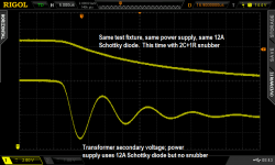
The 20+ page Quasimodo design note is a free .pdf download here on diyAudio, it's attached to post #1 of the Quasimodo thread. The Linear Audio magazine article is not free, but you don't have to buy the whole "book"; they'll happily sell you just that one article as a download file:
edit- here is one photo from the article, plus a couple explanations that I added onto the picture just now (in white)
~
Attachments
Last edited:
- Home
- Amplifiers
- Pass Labs
- Alternate First Watt Power Supply Schematic