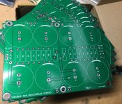
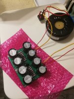
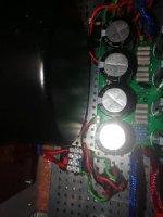
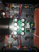
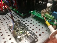
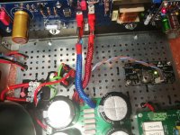
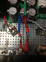
PCB almost mounted. Works without a problem. Unfortunately (this is my first such big DIY project - M2x amp ) and I didn't think well and I used all the gnd audio holes to power the amp boards. I don't know where to connect the "neutral out" to the power supply now.
There is a place for a PCB amp board, but in many threads I read that it is better to connect to the power supply.
Darek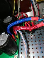
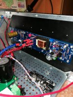
There is a place for a PCB amp board, but in many threads I read that it is better to connect to the power supply.
Darek


I'm not a big proponent of the "connect 0V-out to star-ground" school of thought. It encourages insufficient attention to what's happening.
Andrew (RIP) taught me that power should come back along the same path it went out on.
Note that this *does* in fact mean the star-ground for push-pull designs which don't have 0V going to the amp boards -- although it also means that the amp board's +V-out needs to route first to the star-ground and then (twisted with the 0V-out) to the output terminals.
However, when the 0V is fed to the amp boards, the +V-out and 0V-out should be twisted and both returned to the amp board.
I use GND on M2X PCB also for speakers with no problems at all. I have less than 10 cm wires from last PSU caps to M2X board.
I have been through some PSU modifications and my learning is that if -+rails are not close to 100% identical (numeric value) it is sign of a PSU imbalance that will create some noise in the amp. I was able to get less than 0.02V in rails symmetry and I got rid of some uneven harmonics of 50 Hz (150Hz, 250Hz, 350Hz) and in general very low noise originating from 50 Hz and 100 and their harmonics.
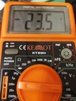
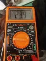
I think 23.5 and 23.9 are more than I would like. At least it should be explained what the reason is (transformer, bridge, filter resistors, bad connection etc.).
I did something wrong, there was smoke and one side of the positive rail is not working. The others have the correct voltage. I checked with a meter and the resistors r1, 2 and 3 are burnt. Before that accident I changed two things.
1. I connected the gnd to the chassis
2. I have shorted the audio gnd output on both sides of the PCB. The outputs were not connected to the amplifier boards.
1. I connected the gnd to the chassis
2. I have shorted the audio gnd output on both sides of the PCB. The outputs were not connected to the amplifier boards.
I replaced damaged resistors. Now it works like it did before the failure. I also made the connection to the housing. Is it possible that shorting these two gnds on both sides of the PCB caused the failure and burning of the resistors? If so, I will be happy to start building further. If not, what could be causing the fault?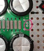

If by "shorting these two gnds on both sides of the PCB" you mean you ran a wire from one side to the other, then no, that shouldn't have any effect. (The ground plane is connected in the middle anyway.)
More pictures might help.
(How high is the board mounted above the chassis bottom?)
More pictures might help.
(How high is the board mounted above the chassis bottom?)
Darrr,
Please show some more pictures of your amp: whole interior, one with all connections to the psu board, and pictures of the connections all all sides of the boards.
Please show some more pictures of your amp: whole interior, one with all connections to the psu board, and pictures of the connections all all sides of the boards.
I shorted the two marked gnd audio on the right and left but not both channels together.If by "shorting these two gnds on both sides of the PCB" you mean you ran a wire from one side to the other, then no, that shouldn't have any effect. (The ground plane is connected in the middle anyway.)
More pictures might help.
(How high is the board mounted above the chassis bottom?)
Shorting those holes on each side definitely didn't do it. They're both connected to the copper ground plane.
Is it possible you temporarily shorted something else? Any wires that might have bent and touched? Any indication of burning anywhere else?
Is it possible you temporarily shorted something else? Any wires that might have bent and touched? Any indication of burning anywhere else?
I didn't notice anything. I soldered the faston terminal to the wire ends on the bottom of the board. I wanted to prepare it as the option for connection to the neutral terminal of the loudspeaker output. The power cords were not connected to the amplifier boards.
Now amplifier on, temperature, bias and offset stable. Idle power +/- 23.5v after connecting to the amp board +/- 22.3V
Now amplifier on, temperature, bias and offset stable. Idle power +/- 23.5v after connecting to the amp board +/- 22.3V
Last edited:
I noticed some copper tape around the center core of the Edcor?
Normally a fluxband is wrapped around the outside of the core to only short the magnetic stray-flux. I would be afraid to short the Edcor by wrap it around the center core?
But if you get it that way from factory it is probably ok. Tape may be isolated at the overlap. Or maybe it is just light reflexes that make it look like copper.
To shield the Edcor from pickup 50 Hz mu-metal is needed.
You're right. It's a copper tape with adhesive. Before I mounted the edcor to the PCB, I checked for a short from the band to the transformer terminals. Now I also checked and it's ok.
Ok, but the copper tape will act like an extra secondary winding and if overlap of tape makes electrical contact (depending if adhesive isolate or not) then it is the same as a shorted secondary and you will probably not get much signal through the Edcor. So if this happens this could be the cause.
Here it shows how an EI-core transformer is built with primary and secondary windings and both are "open":
Calculating mains frequency power transformers
In your case.....you have a potential shorted secondary winding by wrapping conductive tape around the center core of the transformer. But as the adhesive may act like an isolator it may not be a problem. Time will show.
Other can probably chime in to confirm if this could be a problem.....
It depends on what measurement you want from your scope but I guess you just want to look at the voltage in realtime. Now you have set the scope in FFT mode. I guess that is not what you want. You probably want to measure the voltage either in DC or AC coupled mode. So you need a menu where you can set V/div and Sec/div for CH1 and also the coupling (AC or DC)?
- Home
- Amplifiers
- Pass Labs
- Alternate First Watt Power Supply Schematic
