Hi Dennis 🙂darr,
Have you measured the output noise of your amplifier and compared it to what can
be expected? The FW product page gives a noise level of 500uV for the M2:
FIRST WATT PRODUCTS
(I think mine was in the 300uV range.)
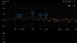
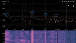
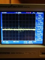
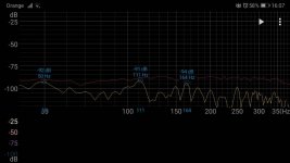
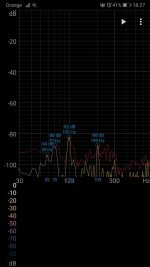
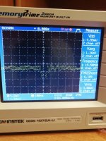
I tried to measure the noise with the oscilloscope but I think I was doing it wrong or too weak oscilloscope. DMM also has too little accuracy. I just hear the noise and I know what frequencies they are from the phone application. I know this is inaccurate but you can find differences in the pictures.
First one Ischikawa board, second Mountain View.
Third is noise on oscilloscope
darrr,
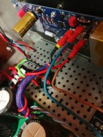
Looking at your wiring diagram I see that you have a ground wire with your V+ and a ground wire with your V- to each amplifier board. That is not a good thing to do. You should only have one ground wire to each board from the power supply and it should be twisted together with the V+ and V- wires for a twisted group of three wires.
As with Jeff, I also believe in twisting wires with their returns, which was strongly advocated by the late Andrew T, RIP.
So I also would twist the speaker out from the board with the ground wire to the speaker protection board and then continue the twisted pair to the speaker output at the back panel. Another thing you could do temporarily is to take the speaker protection board out of the circuit to reduce the variables that may be causing hum. You can put it back in the circuit once you have solved the problem. It may be that it is part of the problem.
Following your advice, I bypassed the speaker protection tabs. I didn't notice the difference, but I'll try to use the loudest input card yet.darrr,
Looking at your wiring diagram I see that you have a ground wire with your V+ and a ground wire with your V- to each amplifier board. That is not a good thing to do. You should only have one ground wire to each board from the power supply and it should be twisted together with the V+ and V- wires for a twisted group of three wires.
As with Jeff, I also believe in twisting wires with their returns, which was strongly advocated by the late Andrew T, RIP.
So I also would twist the speaker out from the board with the ground wire to the speaker protection board and then continue the twisted pair to the speaker output at the back panel. Another thing you could do temporarily is to take the speaker protection board out of the circuit to reduce the variables that may be causing hum. You can put it back in the circuit once you have solved the problem. It may be that it is part of the problem.
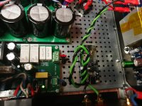
Are you getting noise with some input boards and much less noise with other boards? If that is the case, it appears to me that the issue is with the input boards, not with the power supply or the rest of the amplifier. Jeff has already told you that the ripple of your power supply board is according to design.
You should sort out your issue with measuring the amplifier output with your oscilloscope and get some accurate noise measurements. Did you put an 8 Ohm resistor at the amplifier's speaker output for the measurement? Did you short the amplifier input?
You should sort out your issue with measuring the amplifier output with your oscilloscope and get some accurate noise measurements. Did you put an 8 Ohm resistor at the amplifier's speaker output for the measurement? Did you short the amplifier input?
Thanks to a lot of help from all my good friends in the forum, I came to a conclusion.
I can confirm that the worse PSRR of that input card is the cause of 100hz noise. At the same time, many people wrote that there is no problem using a universal power board from the diyaudio store. Therefore, I am waiting for advice from Jeff whether it is possible to reduce the ripple in some simple way.
I haven't check amplifier with dummy load yet. I was stopped by the desire to explain the strange matter ( for me) of the difference in gnd audio voltages between channels on the CRC board. It took some time and I have not the time to measure it before Christmas. It's not simply thing for noob like me.
I don't think the Universal PSU will make much of a difference -- it has no active suppression either.
More capacitance and more resistance will reduce ripple. I see you're using 22,000uF main caps; you could go to 39,000 or even 47,000uF. What resistance do you measure across the resistors in the PSU?
A c-multiplier would reduce ripple even more, but that's not an easy mod. You'd want something like the Smooth Like Buttah PSU for that.
However, I'm still not sure it's the PSU ripple that's causing your hum. Wiring is more likely. For instance, see this: The SLB (Smooth Like Butter) Active Rect/CRC/Cap Mx Class A Power Supply GB.
Cheers,
Jeff.
It is possible to get M2X very quiet.
Here I measure AC mV at speaker out with speakers connected and preamp powered on....but with no input signal. Input board is IPS6.
I have been through some iterations of the PSU. Mainly the rectifiers which are low Vf Schottky types. PSU is CRCLC and M2X built as mono blocks.
If you can't hear any hum-noise at listening position then be happy for now and enjoy some music. Then built another amp next year and when you have another working amp then go back to M2X and maybe re-built the PSU or just modify it.....if you know what to modify to get it more quiet. Maybe you will know after another built.
Attachments
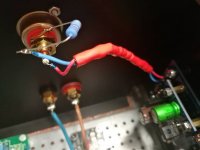
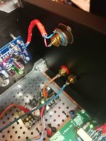
One thing I can't see on any of your pictures is your input wiring. Can you post a picture of that?
Thanks Jeff 🙂
I installed 0.33R and 2k2 on bleeder.
Replacing the snap in capacitors can be a problem. Unless someone knows a good way to do it
Pics input wires.
I improved the wiring a few times, changed the connection method, also without speaker protection cards. I didn't found improvement.
Mountain View cards are the problem, or rather their worse PSRR.


Last edited:
Try unsoldering one of your input grounds and put a 10ohm resistor in the path. (Value isn't critical; anything around that should do.)
darr,
I'd like to go back to Ben's point on noise measurements on your channels.
Can you please try measuring with inputs shorted, and with say, an 8 ohm resistive load?
Try it with both your scope and with a multimeter (set to AC and mV scale)
Being able to quantify the noise level will help you evaluate changes.
The resistor shouldn't matter with the inputs shorted. I wasn't sure if you were getting hum with an input source or not. The resistor is known as a "hum buster" and can fix some hum problems that originate from ground loops between your source component and amplifier.
As a test, remove 2 of the 0R33 resistors out of each bank of 3. So you'll have a single 0R33 on each side of the 2K2.
Don't let it stay on too long as they're going to get a lot hotter this way. But it should tell you if reducing the ripple from the PSU helps.
Don't let it stay on too long as they're going to get a lot hotter this way. But it should tell you if reducing the ripple from the PSU helps.
the amplifier is loaded with an 8r dummy load. How to set up the oscilloscope?The resistor shouldn't matter with the inputs shorted. I wasn't sure if you were getting hum with an input source or not. The resistor is known as a "hum buster" and can fix some hum problems that originate from ground loops between your source component and amplifier.
I did it in safety protection class 2. The amplifier, for example NAD, has then connections to the chassis of each board separately. The connection is via cap 10n or 10n and a 100r resistor in parallelThe resistor shouldn't matter with the inputs shorted. I wasn't sure if you were getting hum with an input source or not. The resistor is known as a "hum buster" and can fix some hum problems that originate from ground loops between your source component and amplifier.
- Home
- Amplifiers
- Pass Labs
- Alternate First Watt Power Supply Schematic
