
I was able to measure the noise at the output of the power supply board. I hope this is a well-done measurement. As you can see in the photos, all rails have similar Vpp ~ 170mV. Now my question. Is this 100hz noise level good, bad or acceptable?
View attachment 896995View attachment 896996
View attachment 896995View attachment 896996
Attachments

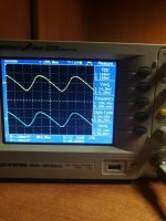
SPICE predicts 174mV from an "ideal" implementation, so I'd say that's pretty dang good.
*If* you had an amp with poorer PSRR (power supply ripple rejection) you'd want to add more capacitance, more resistance, or active filtration -- but Nelson didn't think it was necessary for the M2 so I'd be willing to bet it's got enough PSRR.
(As a counterpoint, look at the F3 schematics. There he added a capacitance multiplier after the PSU.)
That's good. Means that I can continue further work with an amplifier. A big thank you, Jeff, for a great project
@JeffYoung
Hi. Sorry for my English
For a long time I have been struggling with the 100hz hum that makes noise in the speakers in the M2x amplifier. After many attempts, tests etc. I found such a problem with the help friends from the forum. The CRC board, under load, has a potential difference of 6mV per gnd audio between channels. Additionally, there is a difference between the gnd chassis and gnd audio of each individual channel. Here is a picture.
I don't know if you remember but I had a problem and burned the resistors R1,2,3. which I have replaced. What else could go broke and cause this problem? I also tweaked the soldering to make sure I did everything I can.
Can you help me?
Last edited:
If the resistors burned, then there was a lot of current going through them. That current would have had to go through the capacitors too (unless there were a couple of shorts).
Usually when an electrolytic capacitor overheats it boils the electrolyte and pops the casing. But perhaps a lower level of damage just degrades the capacitance? Film capacitors are known to burn holes in their dielectric film, but the dielectric in an aluminium electrolytic (aluminium oxide) has a higher melting point than the aluminium, so I don't know what happens there.
Certainly if the capacitors were no longer taking the ripple out you'd expect some hum at 50hz harmonics. So it fits the symptoms anyway....
which capacitor may be faulty? Is it possible to check a capacitor without desoldering? Could bleeder be a problem?
Could be any of the 4 big ones on the side that the resistors burned. I don't know of a way to check them without de-soldering. (If you have an oscilloscope you could look at the waveform coming out of the supply. If the burned side showed much more ripple than the other then it'd be a pretty good indication that it was the capacitors.)
I don't think a bad bleeder could cause this. It'd either short (in which case it'd burn too) or fail open (in which case it just wouldn't bleed the supply when you turned the power off).
I don't think a bad bleeder could cause this. It'd either short (in which case it'd burn too) or fail open (in which case it just wouldn't bleed the supply when you turned the power off).
@JeffYoung
Hi. Sorry for my English
For a long time I have been struggling with the 100hz hum that makes noise in the speakers in the M2x amplifier. After many attempts, tests etc. I found such a problem with the help friends from the forum. The CRC board, under load, has a potential difference of 6mV per gnd audio between channels. Additionally, there is a difference between the gnd chassis and gnd audio of each individual channel. Here is a picture.
I don't know if you remember but I had a problem and burned the resistors R1,2,3. which I have replaced. What else could go broke and cause this problem? I also tweaked the soldering to make sure I did everything I can.
Can you help me? View attachment 903278
What is the resistance at that connection? 1A though 6 milli-ohms gives 6mV.
Jan
Resistance between gnd of both channels 0R or 16R when I'll turn on the power.
Between gnd audio and chassis gnd 10R (from termistor)
When turn on power they are on right 29.5R and 3.6 on left
Between gnd audio and chassis gnd 10R (from termistor)
When turn on power they are on right 29.5R and 3.6 on left
PS loaded with M2x amplifier. All four power rails look like in this photoCould be any of the 4 big ones on the side that the resistors burned. I don't know of a way to check them without de-soldering. (If you have an oscilloscope you could look at the waveform coming out of the supply. If the burned side showed much more ripple than the other then it'd be a pretty good indication that it was the capacitors.)
I don't think a bad bleeder could cause this. It'd either short (in which case it'd burn too) or fail open (in which case it just wouldn't bleed the supply when you turned the power off).

I don't think there's anything wrong with your PSU. The scope trace looks fine.
Have you tried separating the M2x transformers from the PSU by some distance?
Have you tried separating the M2x transformers from the PSU by some distance?
No I didn't.
I improved the all soldering on PS board Next I did this:
1. I turned on the power supply without load - no difference and 0V between the chassis and the gnd
2. I turned on the power supply with only the left channel. Also 0V
3. I turned on the power supply with only the right channel. 3.4mV between chassis and gnd.
4 I turned on with both channels. 6.8mV on the right and 0.8mV on the left channel between chassis and audio gnd, 6mV between gnd audio left and right channel.
Then I turned the right PS power to the left channel and got the same readings from the left amplifier channel i.e. 3.4mV left channel alone and 6.8mV when both were working.
I think the ground differential is a red herring.
Note Jan's post, and then calculate the resistance over the PSU board width....
Note Jan's post, and then calculate the resistance over the PSU board width....
Sorry, but I don't understand the "red herring".
Maybe I'll show you what all the wiring in the diagram looks like. I do not have PE in the home installation, so I didn't make the grounding and the chassis is not connected to the ground.
Maybe I'll show you what all the wiring in the diagram looks like. I do not have PE in the home installation, so I didn't make the grounding and the chassis is not connected to the ground.
A "red herring" is something that looks like it might matter but actually doesn't.
Under power I suspect your ground is going to go up another couple of mV in the wire between the PSU and the amp board. Everything has some resistance.
Under power I suspect your ground is going to go up another couple of mV in the wire between the PSU and the amp board. Everything has some resistance.
I'm a noob so I'd like to know if I understand you well?
1- 6mv difference between two points of the same audio ground at the two ends of the same PCB is ok and I don't need to look for the reason?
2- 3.4mV difference between gnd audio and chassis which appears only on one channel of the CRC board (it doesn't matter which amplifier board is connected) is ok and I don't have to look for the reason?
3- All this is not affected by power noise and hum?
1) 6mV diff is OK. But it's always good to know the reason. Google "wire resistance calculator" and input the data for your board. Then calculate the voltage drop over that resistance at your bias current (1.3A?).
2) See above.
3) I believe this is correct.
2) See above.
3) I believe this is correct.
darr,
Have you measured the output noise of your amplifier and compared it to what can
be expected? The FW product page gives a noise level of 500uV for the M2:
FIRST WATT PRODUCTS
(I think mine was in the 300uV range.)
Have you measured the output noise of your amplifier and compared it to what can
be expected? The FW product page gives a noise level of 500uV for the M2:
FIRST WATT PRODUCTS
(I think mine was in the 300uV range.)
Thank you Jeff. I do not know what values to enter in this calculator so I will leave this topic since you write that it is ok. By the way, with 18VAC under load 21.5V remains. 2V takes the bridge, isn't the rest of the drop too much? Another thing is the hum of 100hz. In case you don't know, M2x is a clone of M2 with the possibility of using various input cards. There is also a card with Toshiba's original jfet layout which is silent. Another one that I tried already has 100hz hum no longer acceptable. Here is the problem you mentioned. Mountain View does not have the correct PSRR level. Is it possible to reduce the ripple on this crc board or do you need to change the power supply. Replacing capacitors from 22000uF to 33000uf? Maybe adding extra? I am asking for advice.
- Home
- Amplifiers
- Pass Labs
- Alternate First Watt Power Supply Schematic