I have built this line stage using the large output transistors and higher bias. I have also reduced the gain to about x2 as I don't need much gain. I have not yet tested the circuit. I expect to drive it using -+24V PSU or so. My music source is a steamer which outputs about 2Vpp is my guess. I have a crazy idea in mind regarding the volume pot. I want to put it at the output and use a low impedance pot like 220R or so......or maybe even 100R. If stage can drive a headphone it can also drive a 100R pot?
A 220R/100R pot should be able to drive most cables and also most power amp input stages....like M2X etc.?
I want to try to do it this way to have better signal to noise ratio.....better to attenuate a large signal than attenuate a small signal and then amplify it?
I need to ensure that the full input to linestage from my source does not drive linestage into clipping and also that linestage has good performance at the relative high input level?
Could this work well (I guess the same could apply for Whammy but I only use it as preamp)?
I have built this line stage using the large output transistors and higher bias. I have also reduced the gain to about x2 as I don't need much gain. I have not yet tested the circuit. I expect to drive it using -+24V PSU or so. My music source is a steamer which outputs about 2Vpp is my guess. I have a crazy idea in mind regarding the volume pot. I want to put it at the output and use a low impedance pot like 220R or so......or maybe even 100R. If stage can drive a headphone it can also drive a 100R pot?
A 220R/100R pot should be able to drive most cables and also most power amp input stages....like M2X etc.?
I want to try to do it this way to have better signal to noise ratio.....better to attenuate a large signal than attenuate a small signal and then amplify it?
I need to ensure that the full input to linestage from my source does not drive linestage into clipping and also that linestage has good performance at the relative high input level?
Could this work well (I guess the same could apply for Whammy but I only use it as preamp)?
Don't ask me for an equation but a pot on the backside of the preamp will combine with the output impedance of the circuit. I don't think this configuration will help at all with S/N. Without doing any math, I would guess you would get about 20 dB of attenuation at the speaker which isn't much it would be very loud at full attenuation. It may be possible to use an autoformer on the backside but it would need to be custom wound for your application.
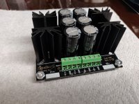
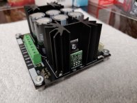
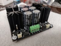
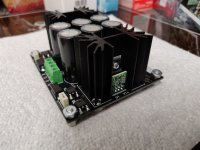
New toy courtesy of Andrew at SparkoS Labs. Will be submitting a write up on my site in the coming weeks. This PSU is configured for (+/-) 18V which is perfect for another Linestage build.
It is designed to take the monolithic 78xx and 79xx regulators and this one comes with the SparkoS ultra low noise discrete regulators which should make this one quiet power supply.")
It is designed to take the monolithic 78xx and 79xx regulators and this one comes with the SparkoS ultra low noise discrete regulators which should make this one quiet power supply.
Attachments
Last edited:
New toy courtesy of Andrew at SparkoS Labs. Will be submitting a write up on my site in the coming weeks. This PSU is configured for (+/-) 18V which is perfect for another Linestage build.
It is designed to take the monolithic 78xx and 79xx regulators and this one comes with the SparkoS ultra low noise discrete regulators which should make this one quiet power supply.
Excellent write up. Looks like an promising line level power supply option!
I need someone with more theory knowledge to help answer a question. I changed R16 from 27k to 90k to increase the gain of line stage. That part works perfectly. Do I need to change the value of C1 from 10pF to approx. 3pF to maintain the same bandwidth or leave it alone?
I really need to figure out how to use a simulator, I know.
I really need to figure out how to use a simulator, I know.
BA2018 evaluation as a headphone amp
I finally got around to converting my BA2018 to large outputs, including the recommended R11, R12, R23 and C1 changes. I also added a switching headphone jack. The result certainly has plenty of drive, and pretty good sound quality, better than most of my other headphone amplifiers. It has about the same clarity and tonal balance as my Whammy when it is fitted with a good monolithic opamp such as the OPA1656ID. That was a surprise, given the discreet front end in the BA2018. That leads me to surmise that the sound of the BA circuit is the sum of its stages. The Whammy with a Burson V6 Classic installed does outperform the BA2018 in terms of detail, openness, and especially overall smoothness and listenabilty on a variety of headphone types.
Maybe it's just my particular power amp inputs but the switching HP jack creates a extremely loud and nasty momentary buzz in the loudspeakers while plugging in the headphones with the amplifier on. Yes, it's easy enough to power down the amp but it does seem to partially defeat the purpose of a switching jack. Referring to Mark Johnson's Noir HPA circuit, I even tried adding some 100 ohm resistors in series with the pre out signal and some 220K load resistors from center pin to shell on the pre-out RCA jacks but it didn't help. I don't see an alternative to powering down the amp other than adding some other switching scheme to short the power amp inputs when they are not in use and prior to HP plug insertion. Shorting the inputs would be necessary since there is low level hum and buzz from the power amp connection cabling when it is not connected to the rest of the internal BA2018 circuitry. Dead silent when connected.
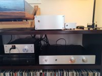
I've more or less finished building my BA2018! Turned it on for the first time yesterday. I am always a little surprised when things work straight away. I was very much in doubt that my soldering skill were up to these tiny SMD transistors.
For this build I used a power supply from fellow diyaudio member Gaz2613. Very easy to put together and with excellent instructions here: Building an improved adjustable Bi-Polar Power Supply! (Updated: 14th Aug 2020) – audiosy.net
I'm also using a Muffsy Relay Input Selector. It supports four inputs, and has mute, standby function, indicator leds and remote control. I added support for motorised volume pot myself. This one is also very easy to build: https://www.muffsy.com/muffsy-relay-input-selector-4.html
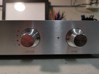
I found a nice chassis on eBay which suited my needs perfectly (although it has some alternative spelling on the input selector knob).
Some remaining things to do: Find a sensible way to mount the IR sensor and I will rewire the IEC socket so that L is switched and fused instead of N.
For this build I used a power supply from fellow diyaudio member Gaz2613. Very easy to put together and with excellent instructions here: Building an improved adjustable Bi-Polar Power Supply! (Updated: 14th Aug 2020) – audiosy.net
I'm also using a Muffsy Relay Input Selector. It supports four inputs, and has mute, standby function, indicator leds and remote control. I added support for motorised volume pot myself. This one is also very easy to build: https://www.muffsy.com/muffsy-relay-input-selector-4.html
I found a nice chassis on eBay which suited my needs perfectly (although it has some alternative spelling on the input selector knob).
Some remaining things to do: Find a sensible way to mount the IR sensor and I will rewire the IEC socket so that L is switched and fused instead of N.
Attachments
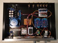
I've more or less finished building my BA2018! Turned it on for the first time yesterday. I am always a little surprised when things work straight away. I was very much in doubt that my soldering skill were up to these tiny SMD transistors.
For this build I used a power supply from fellow diyaudio member Gaz2613. Very easy to put together and with excellent instructions here: Building an improved adjustable Bi-Polar Power Supply! (Updated: 14th Aug 2020) – audiosy.net
I'm also using a Muffsy Relay Input Selector. It supports four inputs, and has mute, standby function, indicator leds and remote control. I added support for motorised volume pot myself. This one is also very easy to build: https://www.muffsy.com/muffsy-relay-input-selector-4.html
I found a nice chassis on eBay which suited my needs perfectly (although it has some alternative spelling on the input selector knob).
Some remaining things to do: Find a sensible way to mount the IR sensor and I will rewire the IEC socket so that L is switched and fused instead of N.
Wow stunning build! It's also nice to see my PSU used in other people's builds. Great work!
If I may ask, what are you using the solid state relay for and the unit to the right of it... what's that?
The small unit to the right of the SSR is a 5 V power supply for the Muffsy. The SSR is used to turn on and off the main power supply from the Muffsy, so that I can wake up the preamplifier from the remote.
Maybe try these: PRP 0.25 Watt Resistors
or these:
Takman Metal Film REY Series 0.25 Watt Resistors
or if you want carbon film:
Takman Carbon Film REX Series 0.25 Watt Resistors
or these:
Takman Metal Film REY Series 0.25 Watt Resistors
or if you want carbon film:
Takman Carbon Film REX Series 0.25 Watt Resistors
- Home
- Amplifiers
- Pass Labs
- Wayne's BA 2018 linestage