Did you see pic? Can you explain to me what this attempt is for?Darrr- can you please attach probe and ground clip across a 100ohm resistor and post a photo ? Would like to see your background.
Flip your FET 180. :
Thank you for your answer. Will try that tomorrow. But I thought drain has to be connected to Vcc and source to ground?
Darr, 6L6 is wondering whether low frequency AC waveforms are ALWAYS present in your lab, using your scope probe, on your scope. So he is asking you to exactly duplicate the conditions in your post #3885. That means:
But this time, connect your probe to a 100 ohm resistor instead of your M2x. This experiment allows 6L6 (and everyone else including you) to see what the background display of your lab gear, actually is.
REGRETTABLY, you didn't do that in #3902. Regrettably you set the horizontal sweep rate to 0.00005 milliseconds per division (500 nanoseconds per division). This is not what 6L6 wanted and it is not what inquiring detectives need to discover clues about what is wrong with your lab gear or your amplifier or both.
People are trying to help you. It would be better if you exhibited a little gratitude.
Vertical gain = 10 mV / division
Horizontal sweep rate = 10 milliseconds per division
Horizontal sweep rate = 10 milliseconds per division
But this time, connect your probe to a 100 ohm resistor instead of your M2x. This experiment allows 6L6 (and everyone else including you) to see what the background display of your lab gear, actually is.
REGRETTABLY, you didn't do that in #3902. Regrettably you set the horizontal sweep rate to 0.00005 milliseconds per division (500 nanoseconds per division). This is not what 6L6 wanted and it is not what inquiring detectives need to discover clues about what is wrong with your lab gear or your amplifier or both.
People are trying to help you. It would be better if you exhibited a little gratitude.
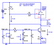
When you operate a J113 at 3 milliamperes of drain to source current, its gate voltage will be less than its source voltage. In other words "Vgs" will be a negative number.
In the figure below I have suggested connecting the positive ("RED") terminal of the voltmeter to the gate voltage, and I have suggested connecting the negative ("BLACK") terminal of the voltmeter to the source voltage. Now the voltmeter will display a negative number and that number will be Vgs.
At 3mA of drain current in a J113, Vgs will ALWAYS be a negative number. That's how Nchannel JFETs work. (Wikipedia article here)
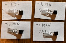
You can write down the measured Vgs numbers, or type them in a spreadsheet, or use speech recognition software to capture them into a text file, or whatever you wish. Exercise your ingenuity, think about it, and do whatever you want.
Me, I wrote the measured values down on paper using a pencil. I did not bother to write down the negative signs because all of the numbers are negative. Why waste time and pencil lead writing eighty minus signs? That was me, exercising MY ingenuity. You are a free agent, you can do it however you wish. Exercise your own ingenuity.
_
In the figure below I have suggested connecting the positive ("RED") terminal of the voltmeter to the gate voltage, and I have suggested connecting the negative ("BLACK") terminal of the voltmeter to the source voltage. Now the voltmeter will display a negative number and that number will be Vgs.
At 3mA of drain current in a J113, Vgs will ALWAYS be a negative number. That's how Nchannel JFETs work. (Wikipedia article here)
You can write down the measured Vgs numbers, or type them in a spreadsheet, or use speech recognition software to capture them into a text file, or whatever you wish. Exercise your ingenuity, think about it, and do whatever you want.
Me, I wrote the measured values down on paper using a pencil. I did not bother to write down the negative signs because all of the numbers are negative. Why waste time and pencil lead writing eighty minus signs? That was me, exercising MY ingenuity. You are a free agent, you can do it however you wish. Exercise your own ingenuity.
_
Attachments
Last edited:
I am sorry if my posts sounded rude. My English is not good and I use the translator too. Obviously my mistake was that I didn't set the range well on the oscilloscope. I didn't understand exactly because this is my first big DIY project and also my first attempts with an oscilloscope (borrowed from a friend) I really appreciate any help and thank you for any help.Darr, 6L6 is wondering whether low frequency AC waveforms are ALWAYS present in your lab, using your scope probe, on your scope. So he is asking you to exactly duplicate the conditions in your post #3885. That means:
Vertical gain = 10 mV / division
Horizontal sweep rate = 10 milliseconds per division
But this time, connect your probe to a 100 ohm resistor instead of your M2x. This experiment allows 6L6 (and everyone else including you) to see what the background display of your lab gear, actually is.
REGRETTABLY, you didn't do that in #3902. Regrettably you set the horizontal sweep rate to 0.00005 milliseconds per division (500 nanoseconds per division). This is not what 6L6 wanted and it is not what inquiring detectives need to discover clues about what is wrong with your lab gear or your amplifier or both.
People are trying to help you. It would be better if you exhibited a little gratitude.
I already have this photo. The second pic is the measurement of the right channel connected to the loudspeaker and the input shorted


The measurement of the amplifier output under the same conditions with the second probe is different
View attachment 898537
Last edited:
Thank you for your answer. Will try that tomorrow. But I thought drain has to be connected to Vcc and source to ground?
He was joking. Do NOT actually flip the FET.
Also maybe post an image here of M2X PCB with Edcor you showed at the other power supply thread. Then other people here can comment the copper tape you have around the core of the Edcor as I think it is not the best to do as it could cause core saturation in Edcor so signal will be attenuated when you connect amp to an AC signal source.
According to your advice, I removed some of the copper band from the edcor. I finished the wiring and tested with an oscilloscope. Now have about 9mVpp on the outputs. One loaded, the other opened. Both inputs are shorteed. Directly from the speaker the noise looks like in the second photo.
Will the edcor cover by mumetal reduce amp noise or the problem is different?


Normally when you wrap copper around an EI transformer it is done at the outside of the "frame" and not around the center core like the primary and secondary windings are.
Mu-metal is good for screening magnetic induced noise which are normally 50/60 Hz from power transformer. You have 100 Hz noise and it must be from the rectifying (ripple noise) and I don't think mu-metal around Edcor will reduce this. But you could try it......and see what happens. 50 Hz noise will be reduced. But I can see that you have a screen around your toroid transformer. If it is steel it will reduce the 50 Hz magnetic field from transformer.
Maybe some experts can comment more about this 🙂
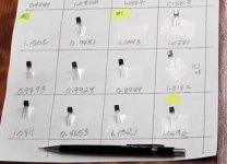
I started the J113 matching for IPS #6 input board. I decided to try out the PEAK DCR tool that has a small curve trace capability if connected to a PC with some dedicated software. I started with single curve traces for each J113 (Vgs on X-axis and Id on Y-axis) with a fixed Vds. The tool only allowed max. 8 VDC for these single traces. On paper it can go to 12 VDC.....but it set the voltage back to 8 VDC for the single trace I defined. But as least all JFETs are measured in same conditions. The first selection was made based on Vgs at the 3mA point (or as close as possible).
I got some candidates for pairs that can be further investigated (maybe 10 candidates for pairs out of 50 J113).
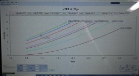
Two candidates for pairs are shown which I will measure further. I will test with curve tracer how close the pair "tracks" same curve for each pair.
I wonder if there is a preferred 3mA Vgs that does is easier to calibrate the IPS #6 boards. Also that I like symmetry my mind says that I should try to get as close to a quad as possible. I also have pair candidates with Vgs at about -0.7 to -0.9 VDC.
The curves at image shows curves for random selected J113 so they differs a lot if just random selected.
I got some candidates for pairs that can be further investigated (maybe 10 candidates for pairs out of 50 J113).
Two candidates for pairs are shown which I will measure further. I will test with curve tracer how close the pair "tracks" same curve for each pair.
I wonder if there is a preferred 3mA Vgs that does is easier to calibrate the IPS #6 boards. Also that I like symmetry my mind says that I should try to get as close to a quad as possible. I also have pair candidates with Vgs at about -0.7 to -0.9 VDC.
The curves at image shows curves for random selected J113 so they differs a lot if just random selected.
Attachments
I had it for a year or so. First time I test it for real "matching purpose". It is also nice just to test if a transistors works.....but for that I also have the cheap Chinese 5$ tools which does a surprisingly good job......
Well ... I don't know what to do next. I have checked the power supply before. The ripple is at 170mV. I tried to connect the "gnd" on both inputs together and the "gnd out" with "gnd" on power supply. No effects and no further ideas.
Check to see that you have followed Best Practices as outlined in these two documents
How to Wire Up an Audio Amplifier
Ground Loops
How to Wire Up an Audio Amplifier
Ground Loops

 Best regards
Thanks MJ for link to the guide.
I read it, but I certainly did not understand everything exactly. I made a wiring diagram and looking at it I noticed that there could be a problem in one place. From the PS on the positive rail, I have a gnd connected to the amplifier pos.gnd and to the speaker protection power supply.
I include this diagram and please comment. Is there anything else that could be causing the problem?
Eh ..... I tried to work carefully and patiently. Unfortunately, too much thought and tweaking connections made me careless. Now I have a bigger problem.
I wanted to test my idea. This time I didn't use the bulb tester and Murphy's law worked. I have connected V + to pos.gnd on one channel. I saw smoke. Before I turned off, the fuse in the socket (2A) was blown. I checked, looks like damaged Q1. Anything else could be broken? R13 measures the same as on the good channel.
I wanted to test my idea. This time I didn't use the bulb tester and Murphy's law worked. I have connected V + to pos.gnd on one channel. I saw smoke. Before I turned off, the fuse in the socket (2A) was blown. I checked, looks like damaged Q1. Anything else could be broken? R13 measures the same as on the good channel.
When you operate a J113 at 3 milliamperes of drain to source current, its gate voltage will be less than its source voltage. In other words "Vgs" will be a negative number.
In the figure below I have suggested connecting the positive ("RED") terminal of the voltmeter to the gate voltage, and I have suggested connecting the negative ("BLACK") terminal of the voltmeter to the source voltage. Now the voltmeter will display a negative number and that number will be Vgs.
At 3mA of drain current in a J113, Vgs will ALWAYS be a negative number. That's how Nchannel JFETs work. (Wikipedia article here)
_
Thank you for your enlighting answer. I soldered my jig on a small piece oft stripboard and had to correct some flaws that i made during the process. After all the tinkering i was not sure if everything was set up correct.
I sucessfully measured all oft my 100 J113 yesterday. I wrote values down by hand but i will enter everything into a spreadsheet, because i like spreadsheets.
Eh ..... I tried to work carefully and patiently. Unfortunately, too much thought and tweaking connections made me careless. Now I have a bigger problem.
I wanted to test my idea. This time I didn't use the bulb tester and Murphy's law worked. I have connected V + to pos.gnd on one channel. I saw smoke. Before I turned off, the fuse in the socket (2A) was blown. I checked, looks like damaged Q1. Anything else could be broken? R13 measures the same as on the good channel.
A couple of year ago I gave myself a Christmas gift:
Metrel Variotransformer bordmodel, MA4804 245V/3,1A
A vario with built-in A and V-meters and an "automatic" fuse. It is a "small" table model. I use that to prevent any damage when I test power supplies etc. I can see if A-meter raise when just a few Volts is applied. Also it is nice to check polarity on caps with just a small voltage. Fast rail fuses is also nice to prevent burnt components on PCB.
A great tool. I have seen so many useful tools but unfortunately it is impossible to buy everything. M2x is supposed to be my Christmas gift ( This is my deal with my wife😉). I do not know if I can make it because this is a new hobby and the troubles are getting bigger and bigger.
- Home
- Amplifiers
- Pass Labs
- The diyAudio First Watt M2x