Claas: Here you go.
1. The R from R14 to Pin2 is the same 220.7 in either lead direction
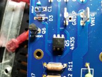
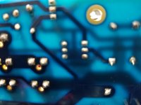
2. Attached are photos showing the orientation and backside soldering. Have done a good bit of this recently and know that both are correct. Keep my Hakko iron at 348 degrees Celsius which is the lowest setting to melt solder. Only touch transistors and optos long enough to make a good, solid connection.
3. Good Continuity between C3 + and Pin 5
4. Good Continuity between C3 - and Pin 4
The left, trouble board may have gotten too hot BUT the right, new board that registers the same low 220 has never been installed or used and has the same low R. So does the older, first left trouble board that got the same run of 4N35 optos. They have been checked with the BoM and Mouser designations and the optos themselves read "4N35."
Thanks, Claas. Am assuming that this suggests the optos are the culprits. Think it unlikely that the transistors, also checked and installed carefully are a problem since the new, right board has the same ones and has not been turned on yet.
1. The R from R14 to Pin2 is the same 220.7 in either lead direction
2. Attached are photos showing the orientation and backside soldering. Have done a good bit of this recently and know that both are correct. Keep my Hakko iron at 348 degrees Celsius which is the lowest setting to melt solder. Only touch transistors and optos long enough to make a good, solid connection.
3. Good Continuity between C3 + and Pin 5
4. Good Continuity between C3 - and Pin 4
The left, trouble board may have gotten too hot BUT the right, new board that registers the same low 220 has never been installed or used and has the same low R. So does the older, first left trouble board that got the same run of 4N35 optos. They have been checked with the BoM and Mouser designations and the optos themselves read "4N35."
Thanks, Claas. Am assuming that this suggests the optos are the culprits. Think it unlikely that the transistors, also checked and installed carefully are a problem since the new, right board has the same ones and has not been turned on yet.
Attachments
When a part-number has lots and lots of letters and digits, manufacturers often stamp a unique coded sequence (with fewer characters!) on the actual part. Check its datasheet to see whether the 595-LM385LPR-1-2 is stamped with a part number, or a code.
(datasheet) here.
Aha! the Table Of Contents (page 2) seems to indicate that Section 13 of the datasheet is the place to look. Clicking on the little blue page number confirms: there it is! Find the column headed "Device Marking". nice.
(datasheet) here.
Aha! the Table Of Contents (page 2) seems to indicate that Section 13 of the datasheet is the place to look. Clicking on the little blue page number confirms: there it is! Find the column headed "Device Marking". nice.
Thanks, Craigl59 !
The 220R over the resistor string from R14 to Pin2 remains a mystery.
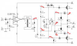
The LM385 1.2 at Q6 and Q7 are actually not transistors, but voltage references, See attached data sheets. I think they are used here as a voltage limiter to protect the Opto LED, kind of a low-voltage Zener Diode.
The symbol on the schematic shows them in this way, too.
Don't know what happens to them if a lot of current is drawn around them, and don't know what defective LM385s would do in this circuit.
It could be instructive to monitor the voltage between Pin1 and Pin2 of the Optocoupler after you switch on the amp. It should start at zero, and rise like 2x the voltage over R13 or R14. Probably a bit less than 2x, because once the Opto LED starts drawing current, some voltage gets lost over R10, R11, R12. And the voltage between Pin1 and Pin2 should always be less than 2.4V (two times the LM385 reference voltage). It should stay there even if the voltage over R13 or R14 continues to rise.
That way, we could make sure that the Opto LED gets the right signal.
How many meters do you have ?
I would only try this measurement with one meter (very small-tipped clip-on probes) at Opto Pin1 and Pin2, and the other meter measuring voltage across R13, so you could switch off before it starts to smoke.
1.2V across 0R47 are actually already 3W (P=U^2/R), so anything higher will have it smoke eventually.
The Opto LED reaches too high current already at about 1.5V (see data sheet maximum ratings and Figure 1). So it might be damaged by now.
Also, 1.2V over 0R47 are 2.55A (Ohm's Law) - that means Q1 and Q2 are dissipating about 60W (P=U*I) each - they will get too hot quickly as well.
What the paragraph above means - once you have found the culprit, and even if the parts are still working, you should probably still change Q1, Q2, R13, R14 and the 4N35, because they are likely to be overstressed.
Regards, Claas
The 220R over the resistor string from R14 to Pin2 remains a mystery.
The LM385 1.2 at Q6 and Q7 are actually not transistors, but voltage references, See attached data sheets. I think they are used here as a voltage limiter to protect the Opto LED, kind of a low-voltage Zener Diode.
The symbol on the schematic shows them in this way, too.
Don't know what happens to them if a lot of current is drawn around them, and don't know what defective LM385s would do in this circuit.
It could be instructive to monitor the voltage between Pin1 and Pin2 of the Optocoupler after you switch on the amp. It should start at zero, and rise like 2x the voltage over R13 or R14. Probably a bit less than 2x, because once the Opto LED starts drawing current, some voltage gets lost over R10, R11, R12. And the voltage between Pin1 and Pin2 should always be less than 2.4V (two times the LM385 reference voltage). It should stay there even if the voltage over R13 or R14 continues to rise.
That way, we could make sure that the Opto LED gets the right signal.
How many meters do you have ?
I would only try this measurement with one meter (very small-tipped clip-on probes) at Opto Pin1 and Pin2, and the other meter measuring voltage across R13, so you could switch off before it starts to smoke.
1.2V across 0R47 are actually already 3W (P=U^2/R), so anything higher will have it smoke eventually.
The Opto LED reaches too high current already at about 1.5V (see data sheet maximum ratings and Figure 1). So it might be damaged by now.
Also, 1.2V over 0R47 are 2.55A (Ohm's Law) - that means Q1 and Q2 are dissipating about 60W (P=U*I) each - they will get too hot quickly as well.
What the paragraph above means - once you have found the culprit, and even if the parts are still working, you should probably still change Q1, Q2, R13, R14 and the 4N35, because they are likely to be overstressed.
Regards, Claas
Attachments
Last edited:
MJ: Yes, checked this page and saw that the LM385LPR-1-2 (specified in the BoM) has a device marking of 385B12. Yet the part Mouser is sending out under the LPR number above reads 385-12 (next line) T1.
Will ask Mouser about this tomorrow when I call them about the Optocoupler and see if it is, in fact, the correct part or a substitute.
What do you think? Have you knowledge about what a low R value from R14 to Pin 2 of the optocoupler would be caused by and/or its reason for variance? Thank, MJ.
Will ask Mouser about this tomorrow when I call them about the Optocoupler and see if it is, in fact, the correct part or a substitute.
What do you think? Have you knowledge about what a low R value from R14 to Pin 2 of the optocoupler would be caused by and/or its reason for variance? Thank, MJ.
Claas: Have one "regular" meter and another MV Meter (used for tape calibrations). Cannot fit either to the RN35 pins as my clips are too large. Am also wary of turning this trouble card on because of damage caused by high current.
You state: "What the paragraph above means - once you have found the culprit, and even if the parts are still working, you should probably still change Q1, Q2, R13, R14 and the 4N35, because they are likely to be overstressed."
This assumes that the parts you are getting are correct. But the RN35s gotten from Mouser appear to be damaged somehow as the new right board, unused, shows the same 220 R having never been used. Will ask Mouser about this tomorrow but do not think that replacing these parts as a whole, when I am not sure they are working properly, will move me forward.
Let me know.
It's been suggested before, this is a good time to pull the 4N35 (if that's what it is) and insert a 6-pin DIP socket. I don't trust myself with not having too heavy a hand when soldering so I use sockets for all DIP packed parts. It sounds like you are being very careful about not overheating but it's still easier to replace a blown DIP pages when it's in a socket.
Thanks, Audiobear. Took the earlier suggestion to heart and ordered 4 of them from Amazon -- should have them next Thursday. Have been doing this with the Tucson cards and a Tandberg Tape machine capstan card (that are both dip-8s) to allow for switching and it works great.
Claas: Ordered another meter and small clip cables from Amazon so I can do your suggested test. Will try this later this week after talking with Mouser. Use the small clip leads with BNC cables for tape equipment and they are superb to hold onto small surfaces.
If any of the gurus on this site have knowledge about a low R value from R14 to Pin 2 of NR35, your help would be timely.
If any of the gurus on this site have knowledge about a low R value from R14 to Pin 2 of NR35, your help would be timely.
That you measure a resistance of 220R between R14 and Opto Pin2 does not indicate that the 4N35 is damaged or the wrong part.
If you look at the schematic, there may be additional current pathways that the resistance-measuring current from you meter might be taking as well, giving a result different from the expected. I don't know what voltage your meter uses to measure resistance, and don't have a clear understanding if the LM385s will have a finite resistance under those circumstances, and if the Opto LED might be conducting.
Anyway, this is not the route to follow at the moment - as I wrote before, a too-low resistance would in a working bias circuit regulate the bias to a lower current than the correct resistance in the string.
We need to find out if the Optocoupler is working as intended - that the Opto LED gets voltage and illuminates the opto transistor when current flows through R13 / R14, and that the opto transistor is discharging the cap C3, so that there would be an equilibrium at 1.3A current through R13 / R14 (600mV).
Which, apparently, isn't happening. The capacitor C3 gets slowly charged as designed, but it doesn't get discharged at the same time by the opto transistor as a counter-action, and no equilibrium is reached.
Also, I wouldn't worry about the parts designation on the LM385. You have the right parts. No need to call Mouser.
Regards, Claas
Claas: Yes, this seems accurate from my repeated experiences:
"Which, apparently, isn't happening. The capacitor C3 gets slowly charged as designed, but it doesn't get discharged at the same time by the opto transistor as a counter-action, and no equilibrium is reached."
Now assuming this is the case, what would the likely issues be? Must restate that a great deal of attention was paid to the construction of the second set of main boards because of the problems with the first, defective left channel board. Feel they are almost certainly correct based on the parts I have. TungstenAudio has looked over the substitute non-polar C3 I had to use and suggests it is OK. So if the equilibrium is not reached are the only possibilities C3 and RN35?
Assume I do the test you so kindly prescribe and it shows the voltage just continuing to get higher and higher -- until smoke starts appearing. Given this assumption, where would you turn next for testing or replacement?
Again, Claas, your help is most appreciated and you should feel proud of helping a fellow DIYer who has little of your expertise. BTW, always enjoy talking with Mouser and will ask them related questions tomorrow.
Claas#2: You state:
"That you measure a resistance of 220R between R14 and Opto Pin2 does not indicate that the 4N35 is damaged or the wrong part."
Understand this but, again, checked a working board with the same meter and it registered 322 ohms (as noted above). So the meter has made the distinction and something other than the meter's current must be responsible for the low R.
Last edited:
Hi Craigl59,
I am suggesting these measurements so we can get a clue if the malfunction of the bias regulation circuit is caused within the 4N35 optocoupler or by something around the optocoupler.
By the way, are the left and right boards for the M2X identical or is there a "Left" and a "Right" board ?
I'm asking in case orientation of 4N35, diodes or LM385 might be different between Left and Right board.
Regards, Claas
Claas: The boards are mirrored and the parts are (sometimes) in different places on the two boards. Suspect they are in the same schematic arrangement but haven't checked this. Must be, though, because only one schematic is supplied.
To recap:
Built a set of the cards about a month ago and the right board worked fine but I switched the mosfets on the left board and it blew immediately. Rebuilt it 3 times and could not get it to work.
Then built a second set of cards, from scratch, with the only part differences C3 and CB3 -- that were backordered. The left board was tried as a substitute for the older, defective board, and had the immediate problem of voltage rise until smoking.
Will check with Mouser tomorrow if there is a better C3 substitute but think that the low R value indicates another problem and that it is the key to fixing the new boards.

From the data sheet it looks like pins 2 to 3 of the 595-LM385LPR-1-2 should test as a diode.
The voltage drop across the opto diode will be around 1.5V, so if your DVM will light up an LED,
it will be able to test the opto diode.
The working board measures 0.440 from 1 to 2 and the same 0.708 from 6 to 4. But this is connected and often a diode must be measured free. So, measured a new, unconnected RN35 and it was like the non-working boards -- 1.077 1 to 2 and 0.708 from 6 to 4.
Does this suggest that something is not connecting to the non-working boards and causing a different voltage than the working board?
Does this suggest that something is not connecting to the non-working boards and causing a different voltage than the working board?
- Home
- Amplifiers
- Pass Labs
- The diyAudio First Watt M2x