Can you contact the diyaudio store to check whether there are known errors on the boards?
Historically, I recall there have been errors on some boards for some amps, and they have still been sold.
This is all the more likely when there are different boards for each channel.
Historically, I recall there have been errors on some boards for some amps, and they have still been sold.
This is all the more likely when there are different boards for each channel.
Last edited:
Hang in there Craigl59. You are getting close. That missing resistance bothers me and I have suspected the reference voltage transistors for some time. If you can unsolder or pull leg three of Q7 and see if the resistance reappears.
Just got time to pull Q7 and the news is disappointing. Checked all of the solder joints on three boards first and they are all good. Will supply a photo if requested. Then removed Q7 and, still, the R from R14 to R11 out is 220 ohms and from R14 to Pin 2 the same 220.
I am completely confused as to how this can take place given the schematic. Any thoughts?
I am completely confused as to how this can take place given the schematic. Any thoughts?
Last edited:
BTW, want to add that the Q7-removed board was the new right board that has never been installed. Chose it to make sure that no earlier electrical problem could affect the result. Also tried adding the mosfets to this new board to see if they made any change in R14 to Pin 2, and they did not.
Am at a loss as to how this R 220 value is happening -- the schematic makes it clear that it should be 321. And, of course, all of the resistors have been tested exhaustively. They are all good.
Am at a loss as to how this R 220 value is happening -- the schematic makes it clear that it should be 321. And, of course, all of the resistors have been tested exhaustively. They are all good.
Last edited:
Perhaps some of below will help to further check Q7 and Q5. All measurements with parts installed on functioning boards. Boards are not mounted to heatsinks or connected to anything. Pulled them from storage.
First thing I check is orientation. I'm sure you've done that. Not sure how the voltage reference would behave if installed backwards, but can't hurt to check.
Checking Q7 alone.
Pin 1 of Q7 to Pin 2 of Q7 - 100R. Pin 3 to Pin 1 or Pin 2 - OL (should be obvious).
Q7 to Q5
Pin 1 Q7 to Pin 1 Q5 - 200R
Pin 1 Q7 to Pin 2 Q5 - 221R
Pin 2 Q7 to Pin 1 Q5 - 100R
Pin 2 Q7 to Pin 2 Q5 - 321R
Both sides of R14 are 100R to pin 1 of Q5.
Both sides of R14 are 320R to to pin 2 of Q5.
Both sides of R14 are 100R to pin 1 of Q7
Both sides of R14 are 0R to pin 2 of Q7
Note - In the schematic within post #1, it is showing pin 1 of the voltage references connected to nothing. For the ones I used, the active pins are pin 1 (anode) and pin 2 (cathode) with pin 3 connected to nothing. Can't hurt to check your spec sheet for the parts you ordered to be sure they're installed in the correct orientation per the traces and schematics. However, if you have anything but an open circuit with some of the measurements you've already taken... that would be odd unless you're measuring only to the middle pin. It's a long shot, but eliminate the easy/obvious first. I doubt it, but you do reference pin numbers in previous posts.... Pin 3 (if you used the part you mentioned earlier) should give you OL / Open circuit for any resistance measurements.
If you need me to take any other measurements, lemme know.
Last edited:
IAIMH: We have tried the measurements you describe and the results are given above. The only problem is R14 to R11 out that is, impossibly, 220ohms now that Q7 is removed. Please read the last 3 pages. The problem must be with the circuit board here. There is a straight path between R14 out and R11 out and it is not responding right with Q7 removed -- it should be 321 ohms but is, instead, 220. This is the issue me must address.
Craigl59
Could you post a really clear big picture of both boards? I have been wondering for some time if the board was the culprit because you've tried everything else. Nonetheless, sometimes other eyes see things that ours don't. Please post the Pix. Thanks.
Could you post a really clear big picture of both boards? I have been wondering for some time if the board was the culprit because you've tried everything else. Nonetheless, sometimes other eyes see things that ours don't. Please post the Pix. Thanks.
And, to amplify your checks, here are the differences; all other measurements agree:
1. Both sides of R14 are 0 ohms to Q7 pin 1
2. Both sides of R14 are 221ohms to Pin 2, Q5
3. P2 of Q7 to Pin 2of Q5 is 221, not 321.
Don't know if this helps or not. This is true for all 3 non-working boards and cannot be the result of parts or build issues.
Thanks for your response.
1. Both sides of R14 are 0 ohms to Q7 pin 1
2. Both sides of R14 are 221ohms to Pin 2, Q5
3. P2 of Q7 to Pin 2of Q5 is 221, not 321.
Don't know if this helps or not. This is true for all 3 non-working boards and cannot be the result of parts or build issues.
Thanks for your response.
If you suspect the board, you can use your eyes and follow the traces and compare their paths to the schematic. You can also remove Q5 and Q6 and along with Q7 removed so that that you can measure the resistors.
You can also compare your board to the board that is pictured on page 1.
I don't know if their are pictures of the back side of the board available but perhaps ItsAllInMyHead can post pictures of the back side of his board for comparison. That way the board may be confirmed, one way or another.
You can also compare your board to the board that is pictured on page 1.
I don't know if their are pictures of the back side of the board available but perhaps ItsAllInMyHead can post pictures of the back side of his board for comparison. That way the board may be confirmed, one way or another.
Last edited:
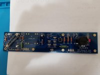
Here you go:
1. NewRight with Q7 removed as described above
2. NewLeft that showed the voltage rise/4N35 inoperative when run
3. Old left that had 3 rebuilds
Let me know and thanks for the help.
1. NewRight with Q7 removed as described above
2. NewLeft that showed the voltage rise/4N35 inoperative when run
3. Old left that had 3 rebuilds
Let me know and thanks for the help.
Attachments


Ben Mah -- already did this when possible for the tracings and all resistors were checked and shown to be correct. Again, the continuity for all 3 boards was thoroughly checked today against the schematic and no issues were found.
The problem is the 220 ohm value from R14 out to R11 out. This cannot be explained by the schematic and is what must be addressed.
The problem is the 220 ohm value from R14 out to R11 out. This cannot be explained by the schematic and is what must be addressed.
Last edited:
Well if the boards have no problems, then the issue has to lie elsewhere.
If the optocoupler is in place and only Q7 is removed, the resistor string of R11, R12, and R14 are parallel to the string of the optocoupler LED, R10, and R13 and then Q6 is also parallel to the string of R10 and R13. So it does not seem like a simple addition to me. But I could be wrong, or I misunderstood your measurement.
If the optocoupler is in place and only Q7 is removed, the resistor string of R11, R12, and R14 are parallel to the string of the optocoupler LED, R10, and R13 and then Q6 is also parallel to the string of R10 and R13. So it does not seem like a simple addition to me. But I could be wrong, or I misunderstood your measurement.
Ben Mah2: Post 5415 above shows the back side in two clear pics for the new Left Board that started the problem investigation.
Not sure what the value of comparing one board to other pics is when the 220 ohm result is the clear issue.
Have reported this to DIY and believe it is their responsibility to respond as to whether or not there have been board build changes and, if so, what they might be.
AGAIN the measurement that does not make sense is R14 out to R11 out. The schematic shows this must be 321 ohms. It is not. It is 220.
And, there is every evidence that the boards do have problems.
Last edited:
Folks, please don't waste your time on any issue other than the 220 versus 321 ohm impossibility. Your suggestions are always appreciated but these do not address what the central problem is.
Here's a clearer picture of the problem. Q7 is removed. R12 in to R12 out is 100 ohms as it should be. R12 in to R11 in is 100 ohms as it should be. R12 in to R12 out is 221 ohms as it should be. BUT R12 in to R11 out is 221 ohms which it CANNOT be. With Q7 removed, there is nothing other than a simple, direct path in the schematic and this must be additive.
How, possibly, can 100 ohms get "lost" if there is not some problem with the board?
How, possibly, can 100 ohms get "lost" if there is not some problem with the board?
R12 is 100 ohms and R11 is 221 ohms. It is confusing because of the numbering and the fourth sentence should read "R11 in to R11 out is 221 ohms as it should be." Sorry for this confusion. But R12 in to R11 out being 221 ohms when it should be 321 is the issue and, as a direct line (with Q7 removed) then it must be additive. Something weird is happening between R12 and R11, or, perhaps, to R11 only. 4N35 (Opto) cannot be affecting this as R11 in to Pin 2 is the correct 221 ohms. But R12 in to Pin 2 is also, 221 ohms which, again, it cannot be -- it should be 321. This is the area that the board is failing in.
Last edited:
- Home
- Amplifiers
- Pass Labs
- The diyAudio First Watt M2x