This is the one you want.
@Diogenio: Mark is right. The correct EDCOR is the 600 Ohm to 15 kOhm version -- not the 10 kOhm version that I attached above. I believe the only reason that was downloaded in my build docs from 2018 is because that was the only version graphed on the EDCOR website. Sorry for any confusion.
heatsink pattern
Go to the DIYaudiostore.com site and fish around for the UMS spec. they have it there. You will have to figure out where you want to place it on the sinks but that is easy. They are predominately on 40mm center They have the compete pattern. The drill is 2.5mm with a 3mm by 5 tap. Set it up so that you drill between the blades and you can drill through if you want to. Lot easier than blind hole. Be careful on the tapping. Don't break it off. There is a kind of tap you can get that looks like a drill which reduces risk of breaking. Don't know what they call it.
Warning. Precision is important. On some boards there is very little wiggle room.
Just did it. Good luck
Don
If you screw up and have to drill & tap a second set of holes, that's not the end of the world. The amp will still work fine and play music. And, since the holes are inside the chassis, nobody will ever see them. Nobody will ever know you performed a do-over. So don't sweat it too much.
If it's a first build worth repeating.
Bolt PCB into place and Mosfets into place before soldering.
If all fits well, then solder the legs while assembled, this minimises strain on the solder joints.
It's a first build of the M2X, but not the first build.
Thanks all the same...
JT
") I don't want to give to much away, but I think this is going to be cool and a major departure from my comfort zone. Gimme a week or so and I'll have something to show ya.
I don't want to give to much away, but I think this is going to be cool and a major departure from my comfort zone. Gimme a week or so and I'll have something to show ya. Nelson Pass builds sleepers too. He builds them, listens to them, tweaks them, asks trusted-ear listeners (30 year friends) to audition them, tweaks them some more, and then releases them to the public. With no advance hints or pre-release marketing or sneak-peek revelations at all.
I hope your sleeper is as awesome as some of Nelson Pass's sleepers have been.
I hope your sleeper is as awesome as some of Nelson Pass's sleepers have been.
Greetings, I just finished my M2X with Ishikawa boards late today (way overdue). I made the recommended modification and used R6 = 37k and RV1 = 20k. I can't get the offset to zero. The closest I can get is about +5V (both channels). I'm assuming I made some bonehead mistake and it's not a matter of just decreasing R7. I read through about 50 pages of this thread. I haven't started to troubleshoot this but thought I'd be lazy and ask what kind of obvious things I must have screwed up. Thanks for your patience.
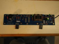
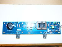
photos
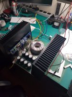
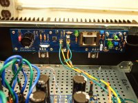
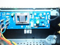
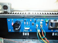
Here are some photos. I hope they show something interesting.
I just getting ready to go over each component and verify against schematic.
Here are some photos. I hope they show something interesting.
I just getting ready to go over each component and verify against schematic.
Attachments
Well, duh... I put a 37 ohm resistor into R6....
Changing it now.
Great catch! Hope this clears up the issue.
- Home
- Amplifiers
- Pass Labs
- The diyAudio First Watt M2x