can someone tell me the total signal gain for the amp?
Non inverting gain is (R4/R1)+1, R4/R1 if it was inverting, i'm just being pedantic, shoot me


Hmmm....
")
Is there a world where we could get our hands on a chassis before Christmas?

I honestly don’t know the answer to that. I’d like to say yes, but will not promise it.
Okay, cool, thanks for chiming in!
So as a noob, I'm trying to put together a WHAMMY BOM that includes everything I will need - even wiring, nuts/bolts, solder, heat paste, etc. Any suggestions to the attached draft BOM are appreciated(basically, I typed up the BOM at #5 and added a few comments and a case). TIA.
Also, I'd like to add a front power indicator, or even better the lit button noted in #293.
Here's my Hammond chassis list:
Mouser Electronics
This list has a nice, filtered AC inlet that is fused. If you want pre-out jacks, add a second pair of RCAs. The extra resistors shown in the photo on the output RCAs are a design taken from the output of Mark Johnson's Noir HPA.
My list has a separate basic LED/resistor and power switch. If you want a lit button, try this:
https://www.mouser.com/ProductDetai...JLQ/ek5pk3DimDobwS98K5GZ7j6HqGCV%2BqqmZnzXQ==
or this:
Amazon.com: APIELE 19mm Latching Push Button Switch 12V DC Angel Eye Halo Ring LED Metal 0.74" 1NO1NC SPDT with Wire Socket Plug (Blue): Automotive
You will still need the external LED voltage dropping resistor since the LED in these switches have an internal resistor value calculated for 12VDC.
If you think you might want to experiment with SMD op amps on an adapter or use the Burson op amps, you should install smaller diameter PS caps (C3 and C4) at the socket location and form the leads with the caps a bit to the side as well. You want lots of room around that socket. These 35V Nichicons will work fine:
UKT1V221MPD Nichicon | Mouser
Attachments
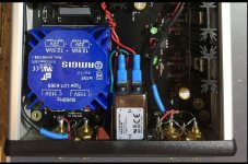
I am trying to debug my WHAMMY amp build. I based it on the BOM posted in this forum. Things are not going very well...
The power supply is working fine -- I used the red "led reference" option and I measure -16.95V and +16.93V on the rails.
The amplifier part, however, is not working properly. Regardless of what is connected to the input, with no load on the output, I see zero DC voltage on the "left out" and some random -1.640V on the "right out"
The question is what is the best way to diagnose this further?
I am using AD823ANZ opamp and IRF9610PBF/IRF610PBF mosfets. I suspect that either the opamp or mosfets might have gotten zapped.
I understand that it's nontrivial to diagnoze things remotely with such little detail, so, any suggestions are appreciated.
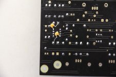
Attaching a photo in case I am missing something stupid.
On the photo -- currently not using C6 and C11 caps on the ps as I didn't receive the right quantity.
Google Photos
The power supply is working fine -- I used the red "led reference" option and I measure -16.95V and +16.93V on the rails.
The amplifier part, however, is not working properly. Regardless of what is connected to the input, with no load on the output, I see zero DC voltage on the "left out" and some random -1.640V on the "right out"
The question is what is the best way to diagnose this further?
I am using AD823ANZ opamp and IRF9610PBF/IRF610PBF mosfets. I suspect that either the opamp or mosfets might have gotten zapped.
I understand that it's nontrivial to diagnoze things remotely with such little detail, so, any suggestions are appreciated.
Attaching a photo in case I am missing something stupid.
On the photo -- currently not using C6 and C11 caps on the ps as I didn't receive the right quantity.
Google Photos
Last edited:
I am trying to debug my WHAMMY amp build. I based it on the BOM posted in this forum. Things are not going very well...
The power supply is working fine -- I used the red "led reference" option and I measure -16.95V and +16.93V on the rails.
The amplifier part, however, is not working properly. Regardless of what is connected to the input, with no load on the output, I see zero DC voltage on the "left out" and some random -1.640V on the "right out"
The question is what is the best way to diagnose this further?
I am using AD823ANZ opamp and IRF9610PBF/IRF610PBF mosfets. I suspect that either the opamp or mosfets might have gotten zapped.
I understand that it's nontrivial to diagnoze things remotely with such little detail, so, any suggestions are appreciated.
Attaching a photo in case I am missing something stupid.
On the photo -- currently not using C6 and C11 caps on the ps as I didn't receive the right quantity.
Google Photos
Are any of the heatsinks getting warm ?
Input voltages at op amp socket - pins 4 and 8 wrt ground?
Input and output wires: I don't think I've seen the shield used for ground.
Last edited:
More general question: what are the bang for the buck mods on this guy (other than rolling op amps)?
TIA
In my Whammy build, I used PRP PR9372 resistors for R7 (R2), R17 (R27), and R39 (R40). For R8 (R4), I used Holco H4 the original UK made Meggitt Holsworthy type. I have used Holcos for the past 25 years in our amplifier restorations and upgrades.
Rick
Thank you sir!
I also added .1uF/200V KEMET XR7 multilayer ceramic caps from opamp pins 4 and 8 to ground for additional bypassing.
Attachments
I am trying to debug my WHAMMY amp build. I based it on the BOM posted in this forum. Things are not going very well...
The power supply is working fine -- I used the red "led reference" option and I measure -16.95V and +16.93V on the rails.
The amplifier part, however, is not working properly. Regardless of what is connected to the input, with no load on the output, I see zero DC voltage on the "left out" and some random -1.640V on the "right out"
The question is what is the best way to diagnose this further?
I am using AD823ANZ opamp and IRF9610PBF/IRF610PBF mosfets. I suspect that either the opamp or mosfets might have gotten zapped.
I understand that it's nontrivial to diagnoze things remotely with such little detail, so, any suggestions are appreciated.
Attaching a photo in case I am missing something stupid.
On the photo -- currently not using C6 and C11 caps on the ps as I didn't receive the right quantity.
Google Photos
Can you post your photos here please? The link you sent requires joining google photos or something, which I don't have time or the desire to do.
Also, are you using the DIYStore Whammy board or your own? You did not state that above.
RE: the MOSFETs, have you tested them with a tester or using this technique?
How to Check a MOSFET Using a Digital Multimeter | Homemade Circuit Projects
--Tom
Should I bother grounding the mu-metal or not necessary?
Careful with that; you don't want to create a shorted turn in the transformer. On the transformers I have, the mu metal/shield around the outside is encased in a final wrapping layer or on some older Plitrons I have, have the mu metal encased in some plastic that is glued to the outside perimeter of the transformer. Presumably both approaches are so they cannot touch the chassis/ground, but maybe someone else on here can clarify. In my experiences, the only thing I've ever grounded in the static shield if it has one, and those generally have a designated lead that you do ground to the chassis.
- Home
- Amplifiers
- Pass Labs
- "WHAMMY" Pass DIY headphone amp guide