Pass DIY Addict
Joined 2000
Paid Member
I would insert a thermistor between PSU ground and earth ground ONLY TO SOLVE A PROBLEM. If you have no problem to solve (hum, ground loop), then you have no need for a thermistor. Instead, make sure you used a heavy gauge wire between PSU 0v point and mains earth.
Some time ago, a PSU cap failed on me (shorted), which drove voltage onto my PSU ground plane. Because of the thermistor between my PSU ground and earth mains, this put quite a bit of excess voltage into my positive power supply rail before the fusing blew, creating a potentially dangerous (for the amp) over-voltage scenario and creating unnecessary fireworks and smoke for me to clean up afterward. With a heavy wire between PSU ground and mains ground, this would not have taken so long to sort itself out and the fuse would have just popped much faster, sparing me from the fireworks.
Some time ago, a PSU cap failed on me (shorted), which drove voltage onto my PSU ground plane. Because of the thermistor between my PSU ground and earth mains, this put quite a bit of excess voltage into my positive power supply rail before the fusing blew, creating a potentially dangerous (for the amp) over-voltage scenario and creating unnecessary fireworks and smoke for me to clean up afterward. With a heavy wire between PSU ground and mains ground, this would not have taken so long to sort itself out and the fuse would have just popped much faster, sparing me from the fireworks.
Hello,
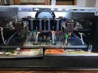
I need your advice because I do not understand a breakdown on the Vfet amp that I just finished.
1 / Before connecting it to the sources and speakers for listening, I turned it on "idle" for more than 6 hours, Bias settings, offset, DC output are in the specifications.
3 / Yesterday at the end of the day so I hooked up to listen for 15 ' and everything worked.
3 / This morning turned on to hear it longer, as soon as the 2 mains fuses of the amp jump, I replace these 2 fuses delayed 1.6A by T 2A and run it on Empty by checking the settings that are in the specifications: everything is ok
4 / Re start-up for listening therefore connected to the sources and HP and there again the fuses T of 2A "jump" as soon as the switch is switched on.
5 / I connect another amp and the whole works, so this problem is not related to the connections of the sources and HP.
Conclusion: the amp works empty and is well regulated, as soon as it connects with the sources and outputs HP, it slams its 2 fuses.
Solution: Should I put fuses with more amperage?
(The transformer is a 400VA so 1.6A should be the norm)
Or do you have another diagnosis?
Christophe
show us some pictures
as I was saying numerous times - Papas simple solution with NTC in series with mains ,is much more universal solution than any soft start based on fixed resistors
value of fixed resistance must be optimized for each case (xformer, c-bank, amp circuitry) ........ and , in best case scenario - relay will go south slower than in worst case scenario
best of both worlds is - using active soft start (relay shorting series resistance) but with group of NTCs instead of series resistor and prolonging relay-ON switch time
almost 100% universal , no need for optimizing
with 400VA Donut - I would not use less than 2AT fuse , in 220Vac area
even better - put 2 or 3 CL60 in series , instead of original resistors in soft start
increase relay-on time
if you point me to exact schematic , I can help with details
disclaimer - I'm just speculating that you have problems with proper setting of soft start and fuse value ......... and everything downstream is OK
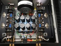
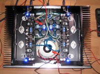
on pics everything looks proper and tidy
increase relay-on time
if you point me to exact schematic , I can help with details
disclaimer - I'm just speculating that you have problems with proper setting of soft start and fuse value ......... and everything downstream is OK
on pics everything looks proper and tidy
Hello
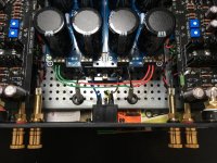
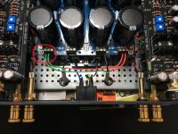
Bingo, after 6 hours of research I found the failure of the amp:
A miserable washer that touched the ground of the PSU. (see the first photo)
Now everything is back in order and the amp works perfectly.
Christophe
Bingo, after 6 hours of research I found the failure of the amp:
A miserable washer that touched the ground of the PSU. (see the first photo)
Now everything is back in order and the amp works perfectly.
Christophe
Attachments

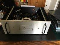
I finished my Vfet amp a few days ago and have been listening to it on my test speakers. I must say that I don't recall ever hearing my old Dynaco A25s sound so good. So thank you Nelson and the DiyAudio team.
However, I think I do have a problem. The right speaker DC offset has a big difference between cold and hot operating condition. The right channel speaker offset measured +156mV cold and -16mV hot. T18 was +1440mV cold and +68mV hot. On the other hand the left channel speaker offset measured +62mV cold and -1mV hot. T18 was +572mV cold and -13mV hot.
This was the third or fourth attempt at setting up the right channel. During one of the other attempts I had output offset of +1mV hot and +165mV cold. I did not record all of the attempts so I don't have numbers for the other instances. It seemed that no matter what I did, there was an approximate 160mV difference between hot and cold speaker offset. The right channel T18 when cold seemed high too.
I also reset the left channel once and I was able to get good results both times.
During the build (with Batch 3 Essentials and Supplemental kits), I measured and recorded the resistances at the test points and they were within 2% or less between channels. I also measured the resistors before installation and they were more or less identical between channels, except for the pots where there were differences of I think 10%. I did not write the values down but I do recall that I noticed that they were not very close matches between channels.
When I first applied power to the front end, most of the test point voltages were very close between the two channels. There were a few that were not as close:
G - T17 .......... left -9.9v ........ right -10.9v
G - T8 ............ left -29.5v ....... right -28.9v
G - T20 ........... left -12.0v........ right -13.1v
V+,V- left was +-29.8, right was +-29.2. Measurements left and right were done at different times of the day.
I also noticed that the component temperature made a big difference to the offsets. The first time that I adjusted both channels, I left the top cover off. When I was satisfied with the numbers, I put the cover on thinking I was done. I measured again later and the offsets had changed considerably. So now I have been running the amp with the cover on and only sliding the cover plate far enough to take the measurements.
Any ideas on what I should check and do to lower the difference between the hot and cold DC offset of the right channel output?
Attachments

with A class amps , without anything having extensive servo-ing function , I'm content even with half Volt when cold
practically , at least what I remember from my own iterations , 350mV at cold is pretty usual with Papamps
practically , at least what I remember from my own iterations , 350mV at cold is pretty usual with Papamps
Thanks for the reassuring answer. I am new to solid state and class A as all my previous builds have been with tubes.
Is the 1440mV at T18 when cold also not unusual and acceptable?
Is the 1440mV at T18 when cold also not unusual and acceptable?
dunno for that ...... I was speaking of output offset
regarding T18 ..... clarify what you mean by "having XX voltage at T18"
edit: now , when I looked at schmtc to refresh memory , I see that T18 is test point , not transistor name 🙂
I presume that you bought input Jfets from Store ?
triple checked all soldering points ........ usual mumbojumbo?
regarding T18 ..... clarify what you mean by "having XX voltage at T18"
edit: now , when I looked at schmtc to refresh memory , I see that T18 is test point , not transistor name 🙂
I presume that you bought input Jfets from Store ?
triple checked all soldering points ........ usual mumbojumbo?
Last edited:
What do you mean by "Jfets?" ?
All parts were part of the DiyAudio Supplemental kit.
All parts were part of the DiyAudio Supplemental kit.
Last edited:
I've been going through the other Vfet thread, Sony VFET Amplifier Part 2, and I see that another Diyer in post #2867 had a reading of 1V at T18 at switch on from cold. So maybe what I am seeing with my amplifier is not abnormal.
Being new to solid state amps, maybe I am just being too cautious.
Being new to solid state amps, maybe I am just being too cautious.
- Home
- Amplifiers
- Pass Labs
- Sony vFET Illustrated build guide