feedback goes over three stages.....
Have you had a chance to test the baby lateral fets yet?
Mine are still in the packaging.
The worst case for the feedback resistor would then be when there is no load on the amplifier output and a very high amplitude input.
Yes and that is only reliability issue of power amp.
Other would be resistor PPM/gedC.
Panasonic claim 200ppm for 5w resistor and 300ppm for 3w resistor.
If I correctly interpreting datasheet for Panasonic resistor, that mean 4-6% delta R, no load vs. full Pd on resistor. .... and it will depend on music material.
May be we can cancel that, if we take care that serial and shunt resistor in feed back network keeping same temperature rise.
here guys..... ")
Peter aka PR made us a Pentecost present, his new idea for a puck output stage controlled by optocouplers.
It is for me a new and interesting way to control the OS stage. Regulation is not as tough as some other solutions but it is stable down to 1 Ohm load.
Please keep in mind this are only drafts and no instructions to build .....
... only Spice ghosts..... not yet proved, but comments welcome!
What do you say ZM, Juma and ....

But the nice with this thread are the many ideas and contributions.....
Peter aka PR made us a Pentecost present, his new idea for a puck output stage controlled by optocouplers.
It is for me a new and interesting way to control the OS stage. Regulation is not as tough as some other solutions but it is stable down to 1 Ohm load.
Please keep in mind this are only drafts and no instructions to build .....
... only Spice ghosts..... not yet proved, but comments welcome!What do you say ZM, Juma and ....
But the nice with this thread are the many ideas and contributions.....
Attachments
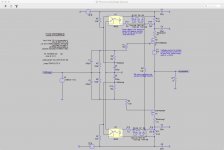

Is there any problem with giving the opto an 80% head start on the voltage it needs. That way the rail resistor could be lowered.
It is even more easy you can take the 0R1 and simply give the R8 a lower value.
Generg, your circuit above, at least on the transistor side of the opto, is exactly the same simple circuit I simulated. I put it aside when you said something about it being more important needing a bias circuit for the second stage. Did you come up with a bias circuit for the second stage then?
nice looking
however , you already know that I'm strictly pursuing concept with no more than 0R1 in rails
also - from my own sims ...... 4x diode is hardly any protection for optoled ;
While there are really effective ways at doing this, I'm with you with regards to impedance on the rails.
I'm super anal about modulated rail voltages.
After trying a few clever circuits, I've gone back to my original version. It's dumb, it's simple, it works, and no worrying about it.
If I was to add resistance there I'd do something crazy like add 100,000uF after it to drop the impedance seen by the drain of the mosfet., which may or may not create some other problem to solve. Could you see a problem with stability putting a huge cap after the biasing resistor.
Edit: I see Generg has added 20,000uF there. Bloody sissy caps. Haha
Last edited:
Hi Rob,
This is a possible solution for the second stage
http://www.diyaudio.com/forums/pass-labs/300233-f4-beast-builders-99.html#post5095771
And as you might have seen Lynn and Zen Mod have solutions too, regulating over all three stages.
I think in the next weeks, months Lynn, Zen Mod Babelfish :--))
And me will have real boards hopefully working.
@ pico: you know in Spice the world is simpler than in reality and 20m might be as good as 100m.....
Is your system running?
Generg, your circuit above, at least on the transistor side of the opto, is exactly the same simple circuit I simulated. I put it aside when you said something about it being more important needing a bias circuit for the second stage. Did you come up with a bias circuit for the second stage then?
Please keep in mind it is pr circuit, not mine. I could not do it.
Your are possibly an electronic engineer like Peter.....:--))
Similar Ideas?
Well no generg, if I had an electronic engineering degree I would have figured out this darn circuit by now. There is no need for me to go back to college at my age. If you have the passion to learn there is lots of information that can be found online, more than you would get from a college degree. I just need to dig in to it and fill in all those large holes in my knowledge.
Yes, a small part of Pr's circuit was the same. My problem is that I am to unsure if it will work in the real world. After I had finished the circuit I read some posts between Lynn and the mighty Zen about servos that made me unsure that it would work.
I have not seen Lynn and Zen's solutions. Where are they posted, do you have a link. That sounds great.
Here is a circuit I did which was inspired somewhat by Wayne's headphone amp.
Attachments

Sorry for deleting last mail there was a wrong picture...
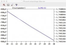
so here again the version that PR made to have an even better regulation.
Replace in the last picture, I add again, R3 and R4 20k by small CCS of 1mA loading the 330uF caps and the 10k R8 by a CCS with 10mA and you get this result for bias variation and the offset for different voltages of the PSU near the values of ZM and Lynn.
Attachments

Is your system running?
Just one channel many weeks ago but, I've been busy with family activities, to case it all up properly.
I'm just starting to get back into things.
Last edited:
With my circuit, 0R1 is the rails is possible, but it appears to require careful selection of the JFET Idss. With higher values of the resistor in the rails the Idss sensitivity is reduced.nice looking
however , you already know that I'm strictly pursuing concept with no more than 0R1 in rails
also - from my own sims ...... 4x diode is hardly any protection for optoled ;
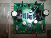
Next week I will hear this version with an optocoupler regulating the second stage without degeneration. Third stage is still "classic" with TL431.
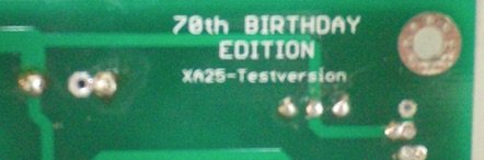
Friends made the board for me as a birthday present.
When this version sounds better to my ears the next step will be a combination of of this frontend and PRs OS with optocouplers or with his current mirror solution that is "fu..ing brilliant".
Friends made the board for me as a birthday present.
When this version sounds better to my ears the next step will be a combination of of this frontend and PRs OS with optocouplers or with his current mirror solution that is "fu..ing brilliant".
Attachments
- Home
- Amplifiers
- Pass Labs
- F4 Beast Builders