If not, check the transformers primary and secondary winding polarity.
As a continuation of your first sentence, I assume you are asking to check the polarity of the Jensen input transformer; not the polarity of the power transformer.
I wouldn't be surprised that it has something to do with the input transformer.
I checked the wiring 3 or 4 times before installing the boards, but could still be an error.
Thanks,
Vince
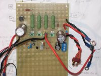
Disconnecting the 220 Ohm feedback resistor on speaker output side stopped the oscillating. Voltage at the drain is more stable and takes a little time to settle.
PS DC output is ~40v.
At power on, the voltage at the signal drain ramps up to 38v and gradually drops to ~20v in both channels. Operating voltage setting is different per side. 3.74v on one channel and 3.86 on the other channel.
Using a spare 5" driver. As the voltage drops, it starts to hum. It's a combo of 60Hz and 120Hz. With no input signal the hum is lower and when I touch the chassis, the 120Hz drop off more. With a source input attached, both 120 and 60Hz gets louder.
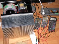
The edge of the power transformer is 17cm (~6.75 in) from the input transformer. I'm guessing that's too close.
PS DC output is ~40v.
At power on, the voltage at the signal drain ramps up to 38v and gradually drops to ~20v in both channels. Operating voltage setting is different per side. 3.74v on one channel and 3.86 on the other channel.
Using a spare 5" driver. As the voltage drops, it starts to hum. It's a combo of 60Hz and 120Hz. With no input signal the hum is lower and when I touch the chassis, the 120Hz drop off more. With a source input attached, both 120 and 60Hz gets louder.
The edge of the power transformer is 17cm (~6.75 in) from the input transformer. I'm guessing that's too close.
Disconnecting the 220 Ohm feedback resistor on speaker output side stopped the oscillating.
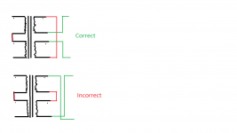
Good, rewire the signal transformer, you have positive feedback.
Voltage at the drain is more stable and takes a little time to settle.
PS DC output is ~40v.
At power on, the voltage at the signal drain ramps up to 38v and gradually drops to ~20v in both channels. Operating voltage setting is different per side. 3.74v on one channel and 3.86 on the other channel.
That's the behaviour I would expect.
Using a spare 5" driver. As the voltage drops, it starts to hum. It's a combo of 60Hz and 120Hz. With no input signal the hum is lower and when I touch the chassis, the 120Hz drop off more. With a source input attached, both 120 and 60Hz gets louder.
The edge of the power transformer is 17cm (~6.75 in) from the input transformer. I'm guessing that's too close.
That's a different problem, and the bane of every builder.
I think I know what i did wrong. I joined the center pins and just flipped the outer secondary pins. Need to flip both leads of the secondary.
I'm fascinated by my own mistake. Despite looking at the schematic many times, I couldn't see it. Even just now when I saw it I wasn't 100% sure.
i moved the dots, not the physical connections. 😀
i moved the dots, not the physical connections. 😀
Attachments
Last edited:
My THF-51S version of the BAF2015 2SK77B is running for the first time today. I have 8R resistor at the speaker output, Vdc=62.5V total, THF-51S Vds=30.0V, I=3.5A.
It is running stable and I had it running for 45 minutes. I adjusted THF-51S Vds to 30.0V because of my power supply voltage is a bit high at 62.5V. After 45 minutes the heat sink temperature was about 62 degrees C.
I have four 4N37 so I tried them all. There was a slight variation in the current, at about 0.1A less with one of the 4N37.
I also used a variac to lower the supply voltage to 60.0V. That did not change the current much.
I would like to lower the current to 3.2A in order to reduce the heat sink temperature a bit. I have read that increasing the resistance between the IXFN140N20P and THF-51S will decrease the current. I have also read that changing the 10K resistor between the drain and gate of IXFN can also change the current.
What should I do to lower the current?
Thanks.
...I have read that increasing the resistance between the IXFN140N20P and THF-51S will decrease the current...
That's what I would do.
My THF-51S version of the BAF2015 2SK77B is running for the first time today. I have 8R resistor at the speaker output, Vdc=62.5V total, THF-51S Vds=30.0V, I=3.5A.
It is running stable and I had it running for 45 minutes. I adjusted THF-51S Vds to 30.0V because of my power supply voltage is a bit high at 62.5V. After 45 minutes the heat sink temperature was about 62 degrees C.
I have four 4N37 so I tried them all. There was a slight variation in the current, at about 0.1A less with one of the 4N37.
I also used a variac to lower the supply voltage to 60.0V. That did not change the current much.
I would like to lower the current to 3.2A in order to reduce the heat sink temperature a bit. I have read that increasing the resistance between the IXFN140N20P and THF-51S will decrease the current. I have also read that changing the 10K resistor between the drain and gate of IXFN can also change the current.
What should I do to lower the current?
Thanks.
you need to inject some additional current in opto-led
two series resistors from positive rail to anode of opto led , bypass lower resistor with cap
calc value of resistors to start with approx. 100uA
handy to put trimpot as one resistor, of course - start with max value
for 30V (half voltage) , that would be ......say for upper resistor put 200k trimpot, lower resistor 100K, bypass lower one with 10-100uF nice elco
that will give 100-300uA
if not enough , scale down
edit: late night , so I forgot that anode is fed from pretty low impedance node
you'll need more injected current , to get enough to opto anode
so just scale resistances down , pretty much peace of cake when you know where to poke 🙂
Last edited:
Don't you ever sleep, ZM?
Thanks for your solution to my problem. I understand what you are saying. I'll need to purchase some trim pots and I'll play around with the lower resistor value also.
For me this is easier than adding resistance between the devices.
I have only one channel (mono block) built. I just hooked a test speaker to it and there is music playing.🙂
Don't you ever sleep, ZM?
Thanks for your solution to my problem. I understand what you are saying. I'll need to purchase some trim pots and I'll play around with the lower resistor value also.
For me this is easier than adding resistance between the devices.
I have only one channel (mono block) built. I just hooked a test speaker to it and there is music playing.🙂
sleep is overrated 🙂
take a look at Babelfish J2, opto part ; pretty much same logic even if slightly broadened - in that case , with trimpot from one end to other , Iq can be set pretty much from really low to several A , while still being rock solid in temp. domain
with simplest (damn clever! Baaaad Pa!) opto-setup , like in M2 and your amp , it's easy upping Iq - just increase resistor in series with opto-led , or put shunt across opto-led
decreasing current is trickier , and only way (without increasing big resistors) is asking for help from above ....... and above ( besides God) is just upper rail

luckily , Buddha is everywhere , so I could make B. J2 opto thingie

edit: I didn't mention another solution , without adding anything - increase resistor going from upper rail to gate , maybe you'll find sweet spot for you , with lower Iq but without starving opto bjt , which could cause instability
Last edited:
Thanks for the explanation, ZM.
I'll try increasing the resistance from upper rail to gate and if unsuccessful, I will go the current injection route.
I'll try increasing the resistance from upper rail to gate and if unsuccessful, I will go the current injection route.
50WSchadeAmp
No Michael, I think it is mandatory for us tube preamp guys who want to build this amplifier. My Homemade 6SN7 Mu-Follower has a relatively high 1500 ohm output impedance
Any help you guys can provide to create a buffered input board would be very much appreciated!
Nothing new on my part. I was just going to lift Nelson's complementary JFET buffer and put it in there. 🙂
I'm interested in the opinion of the group though. Is it overkill?
No Michael, I think it is mandatory for us tube preamp guys who want to build this amplifier. My Homemade 6SN7 Mu-Follower has a relatively high 1500 ohm output impedance
Any help you guys can provide to create a buffered input board would be very much appreciated!
sleep is overrated
The state of being awake causes brain damage.
Only during sleep does the brain and body recuperate.
Brain diseases are ugly. Get your sleep! 🙂
edit: I didn't mention another solution , without adding anything - increase resistor going from upper rail to gate , maybe you'll find sweet spot for you , with lower Iq but without starving opto bjt , which could cause instability
I increased the resistance from 10K to 16K and Iq came down to below 3.3A, and no instability. That's close enough for me.
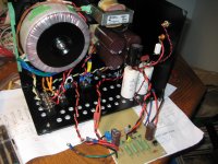
The heat is still quite high so I will baby sit it with two 12V fans. The Antek AN-6450 (50V 600VA) has an unused 18V secondary that will be just right for two fans in series. The heat sink is also meant for forced air cooling anyways. I chose this heat sink so that I could keep both transistors on one heat sink and to keep the mono block footprint small. I was hoping that it was big enough so that I can get away without forced air. It was close but I will baby sit it for peace of mind and less stress on the devices. It will make a good room heater during the winter.
Last night after testing, I played some music through a test speaker (Dynaco A25) and then through my main speaker (Avantgarde Uno from year 2000), the fuse blew. It was a 2.5A SB, the biggest fuse that I had on hand. I have CL60 in series with the transformer primaries so the turn-on surge was reduced, but not enough. The fuse blew after several turn-ons, with cooling in between, so the fuse was probably incrementally damaged during each turn-on. I'll buy some 4A and 5A fuses to try next. The amp sounded good when it was running though.
Now to add the fans, drill cooling holes in the cover plate, and put everything together, and build the other channel.
Attachments
600VA calls for at least 6A3 , in your neck of wood ....... hoping that i'm right that you have same woosy 115Vac mains as your neighbors ?
if you have proper ( not woosy) 230Vac mains , still no go bellow 3A15
depending of fan (internal electronic) , some of them are pushing so much garbage back , polluting entire xformer
don't ask me how I know ........ amp properly silent without fan , when fan is powered , there is brrrrrrrrrrrrrrrrrrrrrrrr
and yes - your sink is for forced cooling - fins too close to do anything properly with natural air flow
that type must have fans mounted on bottom , pushing air longitudinally through sink ; you can even mount plastic/Al wall in front , to increase tunneling
I'll try higher current fuses then. Last time I checked, my AC was 117V but I think it varies through the day.
I am buying DC fans without PWM, so hopefully there will not be much junk. And yes, I will mount the fans under the heat sink.
I am buying DC fans without PWM, so hopefully there will not be much junk. And yes, I will mount the fans under the heat sink.
Pa seems to be amused when I use these on one of our DIY creations.
You'll probably see two of these on the front of my Schade amp.
DC 0-5V Analog Voltmeter Analogue Voltage panel meter SO45 directly Connect | eBay
Regards,
Dan
You'll probably see two of these on the front of my Schade amp.
DC 0-5V Analog Voltmeter Analogue Voltage panel meter SO45 directly Connect | eBay
Regards,
Dan
- Home
- Amplifiers
- Pass Labs
- 50w Single-Ended BAF2015 Schade Enabled