How's this?
Regards,
Dan
I did a bit of "painting" to illustrate my suggestions:
Attachments
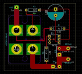

CCS resistors connection in serieAnd the search for resistors continues..
2 x 0.25 = 0.5R
2 x 0.2 = 0.4R on the original schematic
CCS resistors connection in serie
2 x 0.25 = 0.5R
2 x 0.2 = 0.4R on the original schematic
Am I missing something? All I see is .2 and .2?
Regards,
Dan
Attachments
Caddock are 0.25 not 0.20R.
20% of difference between the two values so not the same operation points
20% of difference between the two values so not the same operation points
Caddock are 0.25 not 0.20R.
20% of difference between the two values so not the same operation points
Good point. I'm getting annoyed in my search for resistors. Even when I find 'suitable' candidates they are 10W, 15W, or 30W if you put a heatsink on them.
No heatsink and they are 2W.

What about some current sensing resistors?
Or perhaps just use say five 1 ohm 1+ watt metal film resistors in parallel? (Will take
a bit more room though)
Or perhaps just use say five 1 ohm 1+ watt metal film resistors in parallel? (Will take
a bit more room though)
Could be stuffed in vertical position to save space on the pcb https://www.mouser.ca/ProductDetail...bXrIkmrvidFUHxxUwfKmg7VZBq/jzDfoniTbTeJdPmw==.
I get some Johanson at home and can say is a good solid industrial quality resistors who do the great work in CCS 🙂
Was looking around and I think I found a bargain?
TWW5JR20E Ohmite | Resistors | DigiKey
Regards,
Dan
And the search for resistors continues..
Could be stuffed in vertical position to save space on the pcb https://www.mouser.ca/ProductDetail...bXrIkmrvidFUHxxUwfKmg7VZBq/jzDfoniTbTeJdPmw==.
I get some Johanson at home and can say is a good solid industrial quality resistors who do the great work in CCS 🙂
Some more candidates : https://www.mouser.ca/Passive-Compo...0wsypZ1z0wui7Z1z0wnl8Z1z0vijeZ1z0wljo&FS=True
Last edited:
Was looking around and I think I found a bargain?
Better use 1% resistor tolerance non 5% type imho for this specific application 🙂
Had some time to troubleshoot today, more time tomorrow.
Unloaded voltage is 42v. Loaded is 38v.
Gain mosfet drain is at 38v. When bias voltage is set to 4.7v, the drain operating voltage goes to 0v. Can get the operating voltage close to 18v to 20v by setting bias voltage to 3.89v, but then the drain voltage is unstable, varying rapidly by 2 or 3 volts. Both channels behave the same.
Adjusting the suggested 10k trimmer in series with the 10k fixed resistor near the optical isolator provides no change, and I don't know what to look for when its adjustment is needed.
Resistors on the current source are .3 ohms.
All mosets are Fairchild irfp140s.
output node voltage (approx. 1/2 of rail) is what is important , exact value of bias voltage is irrelevant , part dependent
regarding output node instability ( CCS pumping) , Pa somewhere advised connecting power rresistor in parallel with CCS - practically from rail to output node , thus taking some current from CCS in passive way
sorry , I didn't remember where he wrote that , nor I remembered more important thing - which amount of current he advised to take through resistor
try to find that post
for starters , try with 10% of Iq through resistor .......... in your case that would be around 200mA, right ?
so , 19/0.2 = say 100R , dissipation is 3.6W , so be sure to have 10W of resistors there ........ 3 pcs of 33R/3W in series will do the job
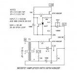
Thank ZM. Are you referring to this?
He said this could also be done on the CCS mosfet.
The DC Drain voltage of the circuit's gain transistor is temperature
dependent, but it generally should be fairly stable if the heat sinking is
adequate - If it's not stable enough you can put a 5 or 10 watt 220 ohm
resistor from Drain to Source to stabilize it better. I don't think you need
the complexity of a servo.
He said this could also be done on the CCS mosfet.
100 ohms worked ok across the current source mosfet, but became extremely hot.
Need to try in 10w version.
Need to try in 10w version.

Tried 100 Ohm and 220 Ohm 10w on current source and signal mosfets, but still have motor boating. The voltage on signal drain mosfet spikes up to 40+ volts with a speaker load.
Amp has a 9K on input and on power supply 44,000uF per channel.
Transformer is 30v 8A per winding. Also tried a transformer per channel with secondaries in parallel.
Maybe it needs more capacitance to make the power supply (PS) stiffer? PS is CRC with four .47 Ohm 3w resistors in parallel.
Nothing had blown up yet, so unless someone has any ideas how to mitigate the oscillating, I'm going to put this project away for a while. I have 4 other amps cooking right now. 🙂
Thanks as always for your help,
Vince
...any ideas how to mitigate the oscillating...
Disconnect the 220R 3W feedback resistor and ground the transformer input, does it still oscillate?
If not, check the transformers primary and secondary winding polarity.
If yes, disconnect the Drain of the lower puck, replace the 'extra' bleed resistor with one that can pass the 3.5A without burning up, and look for oscillation across the resistor.
- Home
- Amplifiers
- Pass Labs
- 50w Single-Ended BAF2015 Schade Enabled